devolo
Door/Window Contact
MT02648
Notification Sensor
01
SD3502
6.51.02
0x0175 (373)
0x0002 (2)
0x000E (14)
ZC10-14090007
2014-09-03 12:36:27.409302
N/A
Enhanced 232 Slave
Reporting Sleeping Slave
Door/Window Contact 3 in 1 (Door/Window, Temperature and Illumination)
The Door/Window Contact MT02648 has door/window, temperature and illumination, 3 sensors function in one,based on Z-Wave technology.
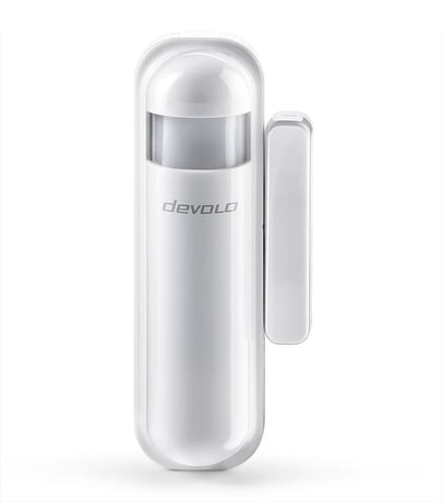
Product Picture


2 - Basic Set Level
Setting the BASIC command value to turn on the light. The 0xFF(-1) means turn on the light. For dimmer equipment 1 to 100 means the light strength. 0 means turn off the light.Size: 1 byte
Default: 255
Minimum: 0
Maximum: 0
Possible values
| From | To | Desription |
|---|---|---|
| 0 | 0 | Send Basic Set Off |
| -1 | -1 | Send Basic Set On |
| 1 | 99 | Send Basic Set Level between 1 and 99 |
4 - Light Threshold
Setting the illumination threshold to turn on the light. When the event triggered and the environment illumination lower then the threshold, the device will turn on the light. 0 means turn off illumination detected function. And never turn on the light. 1 means darkest. 99 means brightest. 100 means turn off illumination detected function. And always turn on the light. Notice: In none test mode, only the value in 1 to 99 will enable the illumination detected function and update the illumination value.Size: 1 byte
Default: 99
Minimum: 0
Maximum: 0
Possible values
| From | To | Desription |
|---|---|---|
| 1 | 99 | Light Threshold Setting |
| 0 | 0 | Turn Off Illumination Detection - Will not turn on the light. |
| 100 | 100 | Turn Off Illumination Detection - The light is always turned on. |
5 - Operation Mode
Operation mode. Using bit mask to control. Bit0: Reserve. Bit1: 1 means test mode, 0 means normal mode. Notice: This bit only effect by the DIP Switch setting to “customer mode”, otherwise it decides by DIP Switch setting to Test or Normal Mode. Bit2: Disable the door/window function. (1:Disable, 0:Enable) Bit3: Setting the temperature scale. 0: Fahrenheit, 1:Celsius Bit4: Disable the illumination report after event triggered. (1:Disable, 0:Enable) Bit5: Disable the temperature report after event triggered. (1:Disable, 0:Enable) Bit6: Reserve. Bit7: Disable the back key release into test mode. (1:Disable, 0:Enable) Notice: The reserve bit is allowed any value, but no effect.Size: 1 byte
Default: 0
Minimum: 0
Maximum: 0
Possible values
| From | To | Desription |
|---|---|---|
| 0 | 1 | Reserved |
| 2 | 2 | Bit Mask - When 1, Test Mode is Enabled, When 0, Test Mode is Disabled |
| 4 | 4 | Bit Mask - When 1, Door/Window function is Disabled, When 0, Door/Window function is Enabled |
| 8 | 8 | Bit Mask - When 1, Temperature Scale is Celsius, When 0, Temperature Scale is Fahrenheit |
| 16 | 16 | Bit Mask - When 1, Illumination Report after event trigger is not sent, When 0, illumination report after trigger is sent. |
| 32 | 32 | Bit Mask - When 1, Temperature report after trigger is not sent, When 0, temperature report after trigger is sent. |
| 64 | 64 | Reserved |
| -128 | -128 | Bit Mask - When 1, Back key release into test mode is disabled, when 0, back key into test mode is enabled. |
6 - Mult-Sensor Function Switch
Multisensor function switch. Using bit to control. Bit0: Disable magnetic integrate illumination to turn ON the lighting nodes in the association group 2. (1:Disable, 0:Enable) Bit1: Reserve. Bit2: Reserve. Bit3: Reserve. Bit4: Disable delay 5 seconds to turn off the light, when door/window closed. (1:Disable, 0:Enable) Bit5: Disable auto turn off the light, after door/window opened to turn on the light. (1:Disable, 0:Enable) Notice: If bit2 is zero, this setting is useless. Notice: If the configuration No.9 is zero, this setting is useless. Bit6: Reserve. Bit7: Reserve. Notice: The reserve bit is allowed any value, but no effect.Size: 1 byte
Default: 4
Minimum: 0
Maximum: 0
Possible values
| From | To | Desription |
|---|---|---|
| 0 | 1 | Bit Mask, When 1, Door opening will not send a signal to the nodes in association group 2, When 0, door opening will cause the lights in association group 2 to be sent a control signal. |
| 2 | 15 | Reserved |
| 16 | 16 | Bit Mask, When 1, Disable the 5 second delay before turning off the light when the door is closed, When 0, enable a 5 second delay before turning off the light when the door is closed. |
| 32 | 32 | Bit Mask, When 1, the automatic turn-off of the light after the light is turned on by a door opening, When 0, the light that is turned on by the door opening will be automatically turned off |
| 64 | -128 | Reserved. |
7 - Customer Function
Customer function switch, using bit control. Bit0: Reserve. Bit1: Reserve. Bit2: Reserve. Bit3: Disable send out BASIC OFF after door closed. (1:Disable, 0:Enable) Bit4: Notification Type, 0: Using Notification Report. 1: Using Sensor Binary Report. Bit5: Disable Multi CC in auto report. (1:Disable, 0:Enable) Bit6: Disable to report battery state when the device triggered. (1:Disable, 0:Enable) Bit7: Reserve. Notice: The reserve bit is allowed any value, but no effect.Size: 1 byte
Default: 4
Minimum: 0
Maximum: 0
Possible values
| From | To | Desription |
|---|---|---|
| 0 | 7 | Reserved |
| 8 | 8 | Bit Mask, When 1, BASIC SET OFF is not sent when the door is closed, When 0, BASIC SET OFF is sent when the door is closed. |
| 16 | 16 | Bit Mask, When 1, Door Opening is reported using Sensor Binary, When 0, Door Opening is reported using Notification Report |
| 32 | 32 | Bit Mask, When 1, Multi CC is Disabled, When 0, Multi CC is Enabled |
| 64 | 64 | Bit Mask, When 1, the battery state is not sent when the device is triggered, when 0, the battery state is sent when the device is triggered. |
| -128 | -128 | Reserved |
9 - Turn Off Light Time
After turn on the lighting, setting the delay time to turn off the lighting when the PIR motion is not detected. 8 seconds per tick, default tick is 4 (32 seconds). 0 means never send turn off light command.Size: 1 byte
Default: 4
Minimum: 0
Maximum: 0
Possible values
| From | To | Desription |
|---|---|---|
| 1 | 127 | Turn Off Light Time (Multiplied by 8) |
| 0 | 0 | Disable automatic light turn off |
10 - Auto Report Battery Time
The interval time for auto report the battery level. 0 means turn off auto report battery. The default value is 12. The tick time can setting by the configuration No.20.Size: 1 byte
Default: 12
Minimum: 0
Maximum: 0
Possible values
| From | To | Desription |
|---|---|---|
| 1 | 127 | Auto Report Battery Time |
| 0 | 0 | Turn Off Automatic Interval Battery Reporting |
11 - Auto Report Door/Window State Time
The interval time for auto report the door/window state. 0 means turn off auto report door/window state. The default value is 12. The tick time can setting by the configuration No.20.Size: 1 byte
Default: 12
Minimum: 0
Maximum: 0
Possible values
| From | To | Desription |
|---|---|---|
| 1 | 127 | Auto Report Door/Window State Time |
| 0 | 0 | Disable automatic interval reporting of the Door/Window state |
12 - Auto Report Illumination Time
The interval time for auto report the illumination. 0 means turn off auto report illumination. The default value is 12. The tick time can setting by the configuration No.20.Size: 1 byte
Default: 12
Minimum: 0
Maximum: 0
Possible values
| From | To | Desription |
|---|---|---|
| 1 | 127 | Auto Report Illumination Time |
| 0 | 0 | Disable automatic illumination reporting interval |
13 - Auto Report Temperature Time
The interval time for auto report the temperature. 0 means turn off auto report temperature. The default value is 12. The tick time can setting by the configuration No.20.Size: 1 byte
Default: 12
Minimum: 0
Maximum: 0
Possible values
| From | To | Desription |
|---|---|---|
| 1 | 127 | Auto Report Temperature Time |
| 0 | 0 | Turn Off Automatic Interval Temperature Reporting |
20 - Auto Report Tick Interval
The interval time for auto report each tick. Setting this configuration will effect configuration No.10, No.11, No.12 and No.13. Caution: Setting to 0 means turn off all auto report function.Size: 1 byte
Default: 30
Minimum: 0
Maximum: 0
Possible values
| From | To | Desription |
|---|---|---|
| 1 | 127 | Auto Report Tick Interval |
| 0 | 0 | Turn Off Automatic Reporting |
21 - Temperature Differential Report
The temperature differential to report. 0 means turn off this function. The unit is Fahrenheit. Enable this function the device will detect every minutes. And when the temperature is over 140 degree Fahrenheit, it will continue report. Enable this functionality will cause some issue please see the detail in the “Temperature Report” section.Size: 1 byte
Default: 1
Minimum: 0
Maximum: 0
Possible values
| From | To | Desription |
|---|---|---|
| 1 | 127 | Temperature Differential Report |
| 0 | 0 | Disable Temperature Differential Reporting |
22 - Illumination Differential Report
The illumination differential to report. 0 means turn off this function. The unit is percentage. Enable this function the device will detect every minutes. Enable this functionality will cause some issue please see the detail in the “Illumination Report” section.Size: 1 byte
Default: 0
Minimum: 0
Maximum: 0
Possible values
| From | To | Desription |
|---|---|---|
| 1 | 99 | Illumination Differential Report |
| 0 | 0 | Turn Off Automatic Differential Illumination Reporting |
There are two tamper keys in the device, one is in the back side, another is in the front side. Both of them can add, remove, reset or association from Z-Wave network. To add into a Z-Wave network: 1. Have Z-Wave Controller entered inclusion mode. 2. Pressing tamper key three times within 1.5 seconds to enter the inclusion mode. 3. After add successful, the device will wake to receive the setting command from Z-Wave Controller about 20 seconds.
There are two tamper keys in the device, one is in the back side, another is in the front side. Both of them can add, remove, reset or association from Z-Wave network. To remove the device from a Z-Wave network: 1. Have Z-Wave Controller entered exclusion mode. 2. Pressing tamper key three times within 1.5 seconds to enter the exclusion mode. Node ID has been excluded.
There are two tamper keys in the device, one is in the back side, another is in the front side. Both of them can add, remove, reset or association from Z-Wave network. Press any key once, the device will awake 10 seconds.
There are two tamper keys in the device, one is in the back side, another is in the front side. Both of them can add, remove, reset or association from Z-Wave network. To reset the device: Notice: Use this procedure only in the event that the primary controller is lost or otherwise inoperable. 1. Pressing tamper key four times within 1.5 seconds and do not release the tamper key in the 4th pressed, and the LED will light ON. 2. After 3 seconds the LED will turn OFF, after that within 2 seconds, release the tamper key. If successful, the LED will light ON one second. Otherwise, the LED will flash once. 3. IDs are excluded and all settings will reset to factory default.