devolo
Scene Switch
MT2652
Wall Controller
1
ZM5202
6.51.01
0x0175 (373)
0x0100 (256)
0x0101 (257)
ZC10-14090021
2014-09-15 17:57:30.00744
N/A
Enhanced 232 Slave
Portable Slave
The MT2652 Scene Switch is a Z-Wave device that can both control other Z-Wave devices and activate scenes.
The MT2652 Scene Switch is a Z-Wave device that can both control other Z-Wave devices and activate scenes. Although it is controlling other devices, the Wall Controller cannot act as Z-Wave network controller (primary or secondary) and will always need a Z-Wave network controller to be included into a Z-Wave network. The device can be used in different modes that are selected by configuration parameters: Control of groups of other Z-Wave devices using 'ON', 'OFF' and Dim commands. Activation of predefined scenes in Gateways or other Z-Wave devices. This device support secure communication when included by a controller that also supports secure communication.
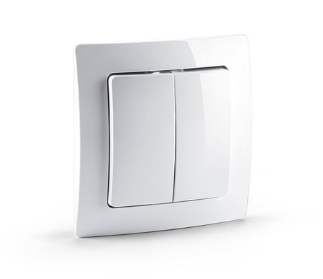
Product Picture


1 - Button 1 and 3 pair mode
In separate mode button 1 works with group A, button 3 with groups C. Click is On, Hold is dimming Up, Double click is Off, Click-Hold is dimming Down. In pair button 1/3 are Up/Down correspondingly. Click is On/Off, Hold is dimming Up/Down. Single clicks works with group A, double click with group C.Size: 1 byte
Default: 1
Minimum: 0
Maximum: 0
Possible values
| From | To | Desription |
|---|---|---|
| 2 | 2 | In pair with double clicks |
| 0 | 0 | seperately |
| 1 | 1 | In pair without double clicks |
2 - Button 2 and 4 pair mode
In separate mode button 2 works with control group B, button 4 with control group D. Click is On, Hold is dimming Up, Double click is Off, Click-Hold is dimming Down. In pair button B/D are Up/Down correspondingly. Click is On/Off, Hold is dimming Up/Down. Single clicks works with group B, double click with group D.Size: 1 byte
Default: 1
Minimum: 0
Maximum: 0
Possible values
| From | To | Desription |
|---|---|---|
| 2 | 2 | In pair with double clicks |
| 1 | 1 | In pair without double clicks |
| 0 | 0 | seperately |
11 - Command to Control Group A
This parameter defines the command to be sent to devices of control group A when the related button is pressedSize: 1 byte
Default: 8
Minimum: 0
Maximum: 0
Possible values
| From | To | Desription |
|---|---|---|
| 5 | 5 | Send Preconfigured Scenes |
| 7 | 7 | Control DoorLock |
| 8 | 8 | Central Scene to Gateway |
| 0 | 0 | Disabled |
| 1 | 1 | Switch On/Off and Dim (send Basic Set and Switch Multilevel) |
| 2 | 2 | Switch On/Off only (send Basic Set) |
| 3 | 3 | Switch All |
| 4 | 4 | Send Scenes |
12 - Command to Control Group B
This parameter defines the command to be sent to devices of control group B when the related button is pressedSize: 1 byte
Default: 8
Minimum: 0
Maximum: 0
Possible values
| From | To | Desription |
|---|---|---|
| 4 | 4 | Send Scenes |
| 3 | 3 | Switch All |
| 5 | 5 | Send Preconfigured Scenes |
| 7 | 7 | Control DoorLock |
| 8 | 8 | Central Scene to Gateway |
| 0 | 0 | Disabled |
| 1 | 1 | Switch On/Off and Dim (send Basic Set and Switch Multilevel) |
| 2 | 2 | Switch On/Off only (send Basic Set) |
13 - Command to Control Group C
This parameter defines the command to be sent to devices of control group C when the related button is pressedSize: 1 byte
Default: 8
Minimum: 0
Maximum: 0
Possible values
| From | To | Desription |
|---|---|---|
| 0 | 0 | Disabled |
| 1 | 1 | Switch On/Off and Dim (send Basic Set and Switch Multilevel) |
| 2 | 2 | Switch On/Off only (send Basic Set) |
| 3 | 3 | Switch All |
| 4 | 4 | Send Scenes |
| 5 | 5 | Send Preconfigured Scenes |
| 7 | 7 | Control DoorLock |
| 8 | 8 | Central Scene to Gateway |
14 - Command to Control Group D
This parameter defines the command to be sent to devices of control group D when the related button is pressedSize: 1 byte
Default: 8
Minimum: 0
Maximum: 0
Possible values
| From | To | Desription |
|---|---|---|
| 1 | 1 | Switch On/Off and Dim (send Basic Set and Switch Multilevel) |
| 0 | 0 | Disabled |
| 2 | 2 | Switch On/Off only (send Basic Set) |
| 3 | 3 | Switch All |
| 4 | 4 | Send Scenes |
| 5 | 5 | Send Preconfigured Scenes |
| 7 | 7 | Control DoorLock |
| 8 | 8 | Central Scene to Gateway |
21 - Send the following Switch All commands
Size: 1 byte
Default: 1
Minimum: 0
Maximum: 0
Possible values
| From | To | Desription |
|---|---|---|
| 1 | 1 | Switch off only |
| 2 | 2 | Switch on only |
| 255 | 255 | Switch all on and off |
22 - Invert buttons
Size: 1 byte
Default: 0
Minimum: 0
Maximum: 0
Possible values
| From | To | Desription |
|---|---|---|
| 1 | 1 | Yes |
| 0 | 0 | No |
25 - Blocks wakeup even when wakeup interval is set
Size: 1 byte
Default: 1
Minimum: 0
Maximum: 0
Possible values
| From | To | Desription |
|---|---|---|
| 0 | 0 | Wakeup is blocked |
| 1 | 1 | Wakeup is not blocked |
30 - Send unsolicited Battery Report on Wake Up
Size: 1 byte
Default: 0
Minimum: 0
Maximum: 0
Possible values
| From | To | Desription |
|---|---|---|
| 0 | 0 | No |
| 1 | 1 | To same node as wake up notification |
| 2 | 2 | Broadcast |
Place your primary controller in inclusion mode by following the manufacturer's instructions, then activate inclusion on the wall controller by pressing any one of the four buttons for one second. Inclusion mode is indicated by the red/green blinking of the LEDs until the timeout occurs after 10 seconds.
Re-Inclusion and Exclusion are performed by pushing button 1 in management mode. Pushing all four buttons for 5 sec. turns the device into management mode (indicated by blinking green LED).
(1) Turn the device into Management Mode by keeping all four buttons pushed for 5 seconds, (2) click on Button 2.
Use this procedure only if the primary controller is missing or otherwise inoperable. (1) Turn the device into Management Mode by keeping all four buttons pushed for 5 seconds, (2) click on Button 3, (3) keep button 4 pushed for 4 seconds.