Philio
In Wall Single relay (1 way) switch module
PAN05-1A
On/Off Power Switch
01
SD3502
6.51.00
0x013C (316)
0x0001 (1)
0x0010 (16)
ZC10-14110005
2014-10-02 14:36:16.224535
N/A
Enhanced 232 Slave
Always On Slave
This in-wall switch module is a transceiver which is a security enabled device which based on Z-Wave Plus technology, and it is fully compatible with any Z-Wave™ enabled network.
This in-wall switch module is a transceiver which is a security enabled device which based on Z-Wave Plus technology, and it is fully compatible with any Z-Wave™ enabled network. Mini size design let the module can easily hide itself into the wall box and that will be good for the house decoration. Since PAN05 supports Security Command Class, it can learn with Secured controller. Its functionality and supported command classes is identical when included as a secure and non-secure device. There are many kind of application by using the module to switch Load On and Off, one main application is the light control. If connect the COM terminal directly to AC Line terminal, the new smart relay calibration technology can reduce the inrush current caused by the load and let the module work perfectly with many kind of light like incandescent, fluorescent and LED light. This module can also connect to alternative power supply like DC 12V to switch on/off 12V MR-16 light.
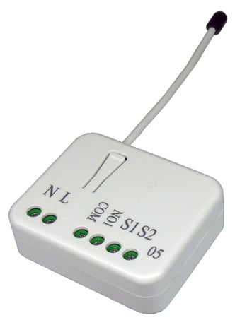
Product Picture


1 - Edge or Pulse mode or Edge-Toggle mode
Manual switch S1 and S2 can set to Edge mode or Pulse mode or Edge-Toggle mode, default value is Edge mode.Size: 1 byte
Default: 1
Minimum: 0
Maximum: 0
Possible values
| From | To | Desription |
|---|---|---|
| 1 | 1 | Edge mode: this mode is suitable for the bi stable wall switch that has indicator point on the switch, and the same position correspond to same state of relay1. If the PAN05 relay change the state because of receiving Z-Wave RF command, it may need two times of change (switch on to off or switch off to on) to let relay back to the correspond state. Manual switch S2 is disabled in this mode. |
| 2 | 2 | Pulse mode: this mode is suitable for the toggle type wall switch to swap the state of Relay1. |
| 3 | 3 | Edge-Toggle mode: this mode is suitable for the normal bi-stable switch, every time when change the state of the wall switch will also swap the state of Relay1. |
2 - Restore switch state mode
Whenever the AC power reconnected to PAN05, it will set the switch to Off、On or Last switch state, default value is Last switch state.Size: 1 byte
Default: 1
Minimum: 0
Maximum: 0
Possible values
| From | To | Desription |
|---|---|---|
| 0 | 0 | Switch off |
| 1 | 1 | Last switch state |
| 2 | 2 | Switch on |
3 - Manual On/Off mode
The On/Off function of S1、S2 and learn switch can be disabled or enabled by this parameter, default value is Enable. But the learning operation won’t be affected.Size: 1 byte
Default: 1
Minimum: 0
Maximum: 0
Possible values
| From | To | Desription |
|---|---|---|
| 0 | 0 | Disable manual On/Off |
| 1 | 1 | Enable manual On/Off |
4 - LED indication mode
This parameter controls the operation of the LED based upon the current state of the switch.Size: 1 byte
Default: 1
Minimum: 0
Maximum: 0
Possible values
| From | To | Desription |
|---|---|---|
| 1 | 1 | Show switch state:LED on for switch on and off for switch off. The default value is Show switch state. |
| 2 | 2 | Show night mode:LED off for switch on and on for switch off. |
| 3 | 3 | One Flash mode:When the state of switch changes, LED will be on only one second, then LED keeps off. |
5 - Auto off timer
This parameter controls the automatic shut-off timer. A value of 0 disables the automatic shut-off feature, a value from 1 to 32767 will represent the number of seconds to elapse until the switch will automatically turn off.Size: 2 bytes
Default: 0
Minimum: 0
Maximum: 0
Possible values
| From | To | Desription |
|---|---|---|
| 0 | 0 | Disable auto off function |
| 1 | 32767 | Set the auto off function to 1 ~ 32767 seconds |
6 - RF Off command mode
This parameter configures how the switch responds to an RF received Off command using BASIC_SET, BINARY_SWITCH_SET, or SWITCH_ALL_OFF. The default value (0) is to turn off the switch.Size: 1 byte
Default: 0
Minimum: 0
Maximum: 0
Possible values
| From | To | Desription |
|---|---|---|
| 1 | 1 | Ignore |
| 2 | 2 | Switch toggle |
| 3 | 3 | Switch on |
| 0 | 0 | Switch off |
1. Put your Z-Wave controller into inclusion mode by following the instructions provided by the controller manufacturer. 2. Pressing Include button of PAN05 three times within 2 seconds will enter inclusion mode.
1. Put your Z-Wave controller into exclusion mode by following the instructions provided by the controller manufacturer. 2. Pressing Include button of PAN05 three times within 2 seconds will enter inclusion mode.
This procedure should only be used in the event that the primary controller is lost or otherwise inoperable. 1. Pressing Include button of PAN05 three times within 2 seconds will enter inclusion mode. 2. Within 1 second, press Include button of PAN05 again for 5 seconds. 3. IDs are excluded.