Building 36
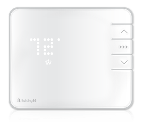
Building 36 Intelligent Thermostat
B36-T10
Thermostat - HVAC
1.0
ZM5202
6.51.02
0x0190 (400)
0x0001 (1)
0x0001 (1)
ZC10-14120002
2014-11-25 20:24:16.250458
N/A
Enhanced 232 Slave
Always On Slave
The Building 36 Intelligent Thermostat allows you to take remote control of your energy use and automate temperature settings — offering a new level of comfort.
The Building 36 Intelligent Thermostat gives you remote access and control of your thermostat. Enjoy effortless energy management, climate and ambiance control, custom automation and measurable results. Create custom smart schedules that automate your thermostat. Receive critical temperature alerts to know instantly when your thermostat reaches preset limits. Save energy by using location-based automation to have your thermostat adjust itself while you're out. This thermostat is part of an entire ecosystem of home automation products. It was built to provide a single integrated solution to give you more from your connected home.


1 - HVAC System Type
The type of HVAC system, either normal or heat pump.Size: 1 byte
Default: 0
Minimum: 0
Maximum: 0
Possible values
| From | To | Desription |
|---|---|---|
| 0 | 0 | Normal |
| 1 | 1 | Heat Pump |
2 - Heat Stages
Number of heat stages if HVAC type is normal or number of auxiliary heat stages if HVAC type is heat pump.Size: 1 byte
Default: 2
Minimum: 0
Maximum: 0
Possible values
| From | To | Desription |
|---|---|---|
| 0 | 3 | Number of Heat Stages |
3 - Number of Cool Stages
Number of cool stages if normal or the number of heat pump stages if heat pumpSize: 1 byte
Default: 2
Minimum: 0
Maximum: 0
Possible values
| From | To | Desription |
|---|---|---|
| 0 | 2 | Cool Stages |
4 - Heat Fuel Type
Denotes the heating fuel type.Size: 1 byte
Default: 1
Minimum: 0
Maximum: 0
Possible values
| From | To | Desription |
|---|---|---|
| 0 | 0 | Fossil Fuel |
| 1 | 1 | Electric (default) |
5 - Calibration Temperature
Used to adjust the ambient room temperature reading up or down to a more accurate value. This may be necessary if the thermostat is installed in a location with abnormal temperature conditions, such as in direct sunlight, near an open window, or on a wall adjacent to an unheated room. The value should be in 1.0 degree Fahrenheit increments. For example, to set the calibration to 2.0F, use value 20.Size: 4 bytes
Default: 0
Minimum: 0
Maximum: 0
Possible values
| From | To | Desription |
|---|---|---|
| -100 | 100 | Calibration Temperature Range (in deg. F) Precision is tenths of a degree. |
6 - Overshoot
The number of degrees the thermostat will keep the system on after meeting the system target. The value should be in 0.5 degree Fahrenheit increments. For example, to set the overshoot to 1.0F, use value 10.Size: 4 bytes
Default: 5
Minimum: 0
Maximum: 0
Possible values
| From | To | Desription |
|---|---|---|
| 0 | 30 | Overshoot Range (in deg. F) Precision is tenths of a degree. |
7 - Swing
The number of degrees the thermostat will add to (for COOL) or remove from (for HEAT) the target before turning the HVAC system on. The value should be in 0.5 degree Fahrenheit increments. For example, to set the swing to 1.0F, use value 10. In precision 10.Size: 4 bytes
Default: 5
Minimum: 0
Maximum: 0
Possible values
| From | To | Desription |
|---|---|---|
| 0 | 30 | Swing Range (in deg. F) Precision is tenths of a degree. |
8 - Heat Staging Delay
In a multistage system, the number of minutes the thermostat will wait before turning on the next heating stage.Size: 1 byte
Default: 5
Minimum: 0
Maximum: 0
Possible values
| From | To | Desription |
|---|---|---|
| 1 | 60 | Heat Staging Delay (in min) |
9 - Cool Staging Delay
In a multistage system, the number of minutes the thermostat will wait before turning on the next cooling stage.Size: 1 byte
Default: 5
Minimum: 0
Maximum: 0
Possible values
| From | To | Desription |
|---|---|---|
| 1 | 60 | Cool Staging Delay (in min) |
10 - Balance Setpoint
If the outside temperature falls below the balance setpoint, the thermostat will only use Auxiliary heating to heat and will not use the heat pump. The value should be in 1.0 degree Fahrenheit increments. For example, to set the balance setpoint to 45.0F, use value 450.Size: 4 bytes
Default: 350
Minimum: 0
Maximum: 0
Possible values
| From | To | Desription |
|---|---|---|
| 0 | 950 | Balance Setpont Range (in deg. F) Precision is tenths of a degree. |
11 - Recovery Settings
In a multistage system, the thermostat will use all stages to reach the target when in comfort mode. When in efficient mode, the thermostat will only use all stages to get within the differential temperature, at which time it will only use a single stage.Size: 1 byte
Default: 1
Minimum: 0
Maximum: 0
Possible values
| From | To | Desription |
|---|---|---|
| 0 | 0 | Comfort |
| 1 | 1 | Efficient |
12 - Fan Circulation Period
The amount of time the fan is in circulation. This feature works with Fan Duty Cycle to determine how long the fan is on during this time.Size: 1 byte
Default: 20
Minimum: 0
Maximum: 0
Possible values
| From | To | Desription |
|---|---|---|
| 10 | 240 | Fan Circulation Period (in min) |
13 - Fan Circulation Duty Cycle
The percentage of the circulation period the fan is on. For example, if the circulation time is 20 minutes, and the duty cycle is 25%, the fan will be on for 5 minutes, then off for 15 minutes until the next cycle.Size: 1 byte
Default: 25
Minimum: 0
Maximum: 0
Possible values
| From | To | Desription |
|---|---|---|
| 0 | 100 | Duty Cycle (percentage) |
14 - Fan Purge Time
The amount of time the thermostat keeps the fan running after turning the system off.Size: 2 bytes
Default: 1
Minimum: 0
Maximum: 0
Possible values
| From | To | Desription |
|---|---|---|
| 1 | 3600 | Purge Time (in s) |
15 - Maximum Heat Setpoint
Maximum heat target allowed. Attempts to set the heat target higher than this value will be ignored. The value should be in 1.0 degree Fahrenheit increments. For example, to set the maximum heat setpoint to 90.0F, use value 900.Size: 4 bytes
Default: 950
Minimum: 0
Maximum: 0
Possible values
| From | To | Desription |
|---|---|---|
| 350 | 950 | Max Heat Setpoint Range (in deg. F) Precision is tenths of a degree. |
16 - Minimum Heat Setpoint
Minimum heat target allowed. Attempts to set the heat target lower than this value will be ignored. The value should be in 1.0 degree Fahrenheit increments. For example, to set the minimum heat setpoint to 61.0F, use value 610.Size: 4 bytes
Default: 350
Minimum: 0
Maximum: 0
Possible values
| From | To | Desription |
|---|---|---|
| 350 | 950 | Min Heat Setpoint Range (in deg. F) Precision is tenths of a degree. |
17 - Maximum Cool Setpoint
Maximum cool target allowed. Attempts to set the cool target higher than this value will be ignored. The value should be in 1.0 degree Fahrenheit increments. For example, to set the maximum cool setpoint to 80.0F, use value 800.Size: 4 bytes
Default: 950
Minimum: 0
Maximum: 0
Possible values
| From | To | Desription |
|---|---|---|
| 500 | 950 | Max Cool Setpoint Range(in deg. F) Precision is tenths of a degree. |
18 - Minimum Cool Setpoint
Minimum cool target allowed. Attempts to set the cool target lower than this value will be ignored. The value should be in 1.0 degree Fahrenheit increments. For example, to set the minimum coolsetpoint to 67.0F, use value 670.Size: 4 bytes
Default: 500
Minimum: 0
Maximum: 0
Possible values
| From | To | Desription |
|---|---|---|
| 500 | 950 | Min Cool Setpoint (in deg. F) Precision is tenths of a degree. |
19 - Thermostat Lock
If enabled, local thermostat control is disabled.Size: 1 byte
Default: 0
Minimum: 0
Maximum: 0
Possible values
| From | To | Desription |
|---|---|---|
| 0 | 0 | Disabled |
| 1 | 1 | Enabled |
20 - Compressor Delay
Minimum interval the thermostat will keep the thermostat off. Rapid cycling of the compressor may cause damage to the compressor.Size: 1 byte
Default: 5
Minimum: 0
Maximum: 0
Possible values
| From | To | Desription |
|---|---|---|
| 0 | 60 | Compressor Delay (in min) |
21 - Demand Response Period
This parameter is used in conjunction with the Demand Response Duty Cycle to limit the amount of time the thermostat may run the HVAC system.Size: 1 byte
Default: 10
Minimum: 0
Maximum: 0
Possible values
| From | To | Desription |
|---|---|---|
| 10 | 240 | Demand Response Period (in min) |
22 - Demand Response Duty Cycle
This parameter is used in conjunction with the Demand Response Period to limit the amount of time the thermostat may run the HVAC system.Size: 1 byte
Default: 25
Minimum: 0
Maximum: 0
Possible values
| From | To | Desription |
|---|---|---|
| 0 | 100 | Demand Response Duty Cycle (percentage) |
23 - Temperature Display Units
This parameter controls what thermostat units are displayed on the thermostat screen. It is independent of the temperature units used on the Z-Wave network.Size: 1 byte
Default: 1
Minimum: 0
Maximum: 0
Possible values
| From | To | Desription |
|---|---|---|
| 0 | 0 | Celsius |
| 1 | 1 | Farenheit |
24 - HVAC Modes Enabled
Control which HVAC modes are enabled.Size: 1 byte
Default: 15
Minimum: 0
Maximum: 0
Possible values
| From | To | Desription |
|---|---|---|
| 3 | 3 | Off, Heat |
| 5 | 5 | Off, Cool |
| 7 | 7 | Off, Heat, Cool |
| 15 | 15 | Off, Heat, Cool, Auto |
| 31 | 31 | Off, Heat, Cool, Auto, Emergency Heat |
| 23 | 23 | Off, Heat, Cool, Emergency Heat |
| 19 | 19 | Off, Heat, Emergency Heat |
25 - Configurable Terminal Setting
Control the function of the configurable terminal on the thermostat.Size: 1 byte
Default: 0
Minimum: 0
Maximum: 0
Possible values
| From | To | Desription |
|---|---|---|
| 0 | 0 | Disabled |
| 1 | 1 | W3 |
| 2 | 2 | H |
| 3 | 3 | DH |
26 - Power Source
This is a read only parameter that shows the current power source used by the thermostat.Size: 1 byte
Default: 0
Minimum: 0
Maximum: 0
Possible values
| From | To | Desription |
|---|---|---|
| 0 | 0 | Battery |
| 1 | 1 | C-Wire |
27 - Battery Alert Threshold Low
Low battery alert threshold.Size: 1 byte
Default: 30
Minimum: 0
Maximum: 0
Possible values
| From | To | Desription |
|---|---|---|
| 0 | 100 | Battery Alert Range (percentage) |
28 - Battery Alert Threshold Very Low
Very low battery alert threshold.Size: 1 byte
Default: 15
Minimum: 0
Maximum: 0
Possible values
| From | To | Desription |
|---|---|---|
| 0 | 100 | Very Low Battery Alert Range (percentage) |
30 - Remote Temperature Enable
If enabled, the thermostat will use the remote temperature instead of the local measured value.Size: 1 byte
Default: 0
Minimum: 0
Maximum: 0
Possible values
| From | To | Desription |
|---|---|---|
| 0 | 0 | Disabled |
| 1 | 1 | Enabled |
31 - Heat Differential
The number of degrees it takes to activate the next stage of heating after the first stage has been turned on. The value should be in 0.5 degree Fahrenheit increments. For example, to set the heat differential to 1.5F, use value 15.Size: 4 bytes
Default: 30
Minimum: 0
Maximum: 0
Possible values
| From | To | Desription |
|---|---|---|
| 10 | 100 | Heat Differential (in deg. F) Precision is tenths of a degree. |
32 - Cool Differential
The number of degrees it takes to activate the next stage of cooling after the first stage has been turned on. The value should be in 0.5 degree Fahrenheit increments. For example, to set the cool differential to 2.5F, use value 25.Size: 4 bytes
Default: 30
Minimum: 0
Maximum: 0
Possible values
| From | To | Desription |
|---|---|---|
| 10 | 100 | Cool Differential (in deg. F) Precision is tenths of a degree. |
33 - Temperature Reporting Threshold
The minimum number of degrees the ambient temperature must change between reported temperature values. The value should be in 0.5 degree Fahrenheit increments. For example, to set the temperature reporting threshold to 1.5F, use value 15.Size: 4 bytes
Default: 10
Minimum: 0
Maximum: 0
Possible values
| From | To | Desription |
|---|---|---|
| 5 | 20 | Temperature Reporting Range (in deg. F) Precision is tenths of a degree. |
34 - O/B Select
O/B terminal setting that should be set to match which the wire connected to the O/B terminal.Size: 1 byte
Default: 1
Minimum: 0
Maximum: 0
Possible values
| From | To | Desription |
|---|---|---|
| 0 | 0 | O/B Terminal acts as B terminal, closed when cooling |
| 1 | 1 | O/B Terminal acts as O terminal, closed when heating |
35 - Z-Wave Echo Association Reports
When enabled, the thermostat will report all changes to the thermostat mode, thermostat fan mode, and thermostat setpoint, even when change was caused by commands from Z-wave.Size: 1 byte
Default: 0
Minimum: 0
Maximum: 0
Possible values
| From | To | Desription |
|---|---|---|
| 0 | 0 | Disabled |
| 1 | 1 | Enabled |
1. Put the thermostat in OFF mode (No mode icons are lit). 2. Put the Z-Wave controller into add mode. Refer to the controller documentation for more information. 3. Press and hold the DOWN button on the thermostat to begin inclusion. Release the button when the RADIO icon lights up. 4. When the RADIO icon becomes solid, the thermostat has been added.
1. Put the thermostat in OFF mode (No mode icons are lit). 2. Press and hold the remove button on the Z-Wave controller. Refer to controller documentation for more information. 3. Press and hold the DOWN button on the thermostat to enter exclusion mode. Release the button when the RADIO icon lights up. 4. When the RADIO icon becomes solid the thermostat has now been successfully removed from the network.
Please use this procedure only when your primary controller is missing or otherwise inoperable. 1. Put the thermostat in OFF mode (No mode icons are lit). 2. Press and hold the UP button to show the firmware versions. 3. Once the firmware versions are shown, press and hold the DOWN button to enter RST mode. The thermostat should display ""RST"".