FIBARO
FIBARO Smoke Sensor
FGSD-002
Notification Sensor
2
ZM5202
6.51.06
0x010F (271)
0x0C02 (3074)
0x1002 (4098)
ZC10-15070004
2015-07-01 07:40:29.893
N/A
Enhanced 232 Slave
Reporting Sleeping Slave
A battery powered smoke detector which gives protection from flaming and smoldering fires.
The FIBARO Smoke Sensor is a universal, ultra-light, perfectly designed, optical Z-Wave smoke detector. Fire alarm is signaled by sound, visual indicator blinking and alarm reports sent to the other devices within Z-wave network. The optical sensor detects smoke at an early stage of fire, often before flames appear and temperature starts to rise significantly. Moreover, the device has a built-in temperature sensor, which is adjustable to allow detection of fire by exceeding given temperature threshold. The FIBARO Smoke Sensor is a battery powered device designed to be placed on the wall or ceiling. Visual indicator signals fire, operating mode and it is used to check if the device is within the Z-wave network using a built-in Z-Wave range tester. The Smoke Sensor is designed to operate in confined spaces, under normal conditions (lacking of smoke, dust or condensed water vapor). Product video: https://www.youtube.com/watch?v=50QGfkdUtns
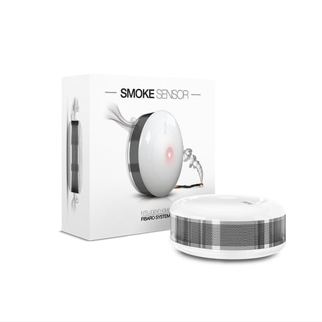
Product Picture


1 - Fibaro Smoke Sensor sensitivity
There are 3 levels of sensitivity to smoke presence. Level 1 means the highest sensitivity. Rising the parameter value lowers the sensitivity to smoke presence. 1 - HIGH sensivity 2 - MEDIUM sensivity 3 - LOW sensivitySize: 1 byte
Default: 2
Minimum: 0
Maximum: 0
Possible values
| From | To | Desription |
|---|---|---|
| 1 | 3 |
2 - Z-Wave notifications status
This parameter allows to activate excess temperature and/or casing opening notifications sent to the main controller. 0 - all notifications disabled, 1 - casing opening notification enabled, 2 - exceeding temperature threshold notification enabled. Parameter values may be combined, e.g. 1+2=3, means that all notifications are enabled.Size: 1 byte
Default: 0
Minimum: 0
Maximum: 0
Possible values
| From | To | Desription |
|---|---|---|
| 0 | 3 |
3 - Visual indicator notifications status
This parameter allows to activate visual indications but does not apply to major alarms, such as Fire, Trouble and Low battery alarm. 0 - all notifications disabled, 1 - casing opening notification enabled, 2 - exceeding temperature threshold notification enabled, 4 - lack of Z-Wave range notification. Parameter values may be combined, e.g. 1+2+4=7, means that all notifications are enabled.Size: 1 byte
Default: 0
Minimum: 0
Maximum: 0
Possible values
| From | To | Desription |
|---|---|---|
| 0 | 7 |
4 - Sound notifications status
This parameter allows to activate sound signals but does not apply to major alarms, such as Fire, Trouble and Low battery alarm. 0 - all notifications disabled, 1 - casing opening notification enabled, 2 - exceeding temperature threshold notification enabled, 4 - lack of Z-Wave range notification. Parameter values may be combined, e.g. 1+2+4=7, means that all notifications are enabled.Size: 1 byte
Default: 0
Minimum: 0
Maximum: 0
Possible values
| From | To | Desription |
|---|---|---|
| 0 | 7 |
10 - Configuration of control frames in BASIC command class
This parameter defines which frames will be sent in the 2-nd Association Group (SMOKE ALARM). The values of BASIC ON and BASIC OFF frames may be defined as described in further parameters. 0 -BASIC ON & BASIC OFF enabled 1- BASIC ON enabled 2 - BASIC OFF enabledSize: 1 byte
Default: 0
Minimum: 0
Maximum: 0
Possible values
| From | To | Desription |
|---|---|---|
| 0 | 2 |
11 - BASIC ON frame value
BASIC ON frame is sent in case of smoke presence detection and Fire Alarm triggering. Its value is defined by the parameter. 0 turn off the device 1-99 set the device to 1-99% 255 set the last statusSize: 2 bytes
Default: 255
Minimum: 0
Maximum: 0
Possible values
| From | To | Desription |
|---|---|---|
| 0 | 99 | |
| 255 | 255 |
12 - BASIC OFF frame value
BASIC OFF frame is sent in case of Fire Alarm cancellation. Its value is defined by the parameter. 0 turn off the device 1-99 set the device to 1-99% 255 set the last statusSize: 2 bytes
Default: 0
Minimum: 0
Maximum: 0
Possible values
| From | To | Desription |
|---|---|---|
| 255 | 255 | |
| 0 | 99 |
13 - Alarm broadcast
A value other than 0 means that alarms are being sent in broadcast mode, i.e. to all devices within a Fibaro Smoke Sensor’s range. 0 – broadcast inactive, 1 – SMOKE ALARM command broadcast (2-nd & 4-th Association Group) active; casing opening notification broadcast (3-rd & 5-th Association Group) inactive, 2 – SMOKE ALARM command broadcast (2-nd & 4-th Association Group) inactive; casing opening notification broadcast (3-rd & 5-th Association Group) active, 3 – SMOKE ALARM command broadcast (2-nd & 4-th Association Group) active; casing opening notification broadcast (3-rd & 5-th Association Group) active. NOTE: Operating in Z-Wave network security mode automatically disables sending alarms in broadcast mode.Size: 1 byte
Default: 0
Minimum: 0
Maximum: 0
Possible values
| From | To | Desription |
|---|---|---|
| 0 | 3 |
14 - Associations in Z-Wave network security mode
This parameter defines how commands are sent in specified association groups: as secure or non-secure. Parameter is active only in Z-Wave network security mode. It doesn’t apply to 1st Lifeline group. 0 - all groups sent as non-secure, 1 - 2nd group sent as secure, 2 - 3rd group sent as secure, 4 - 4th group sent as secure, 8 - 5th group sent as secure. Parameter values may be combined, e.g. 1+2=3 means that 2nd & 3rd group are sent as secure.Size: 1 byte
Default: 15
Minimum: 0
Maximum: 0
Possible values
| From | To | Desription |
|---|---|---|
| 0 | 15 |
20 - Temperature report interval
Time interval between consecutive temperature reports. Report is sent when new temperature value is different from the one previously reported - according to the set hysteresis (parameter 21). Temperature reports can be also sent as a result of polling. 0 reports inactive 1 - 8640 (multiply by 10 seconds) [10s-24h]Size: 2 bytes
Default: 1
Minimum: 0
Maximum: 0
Possible values
| From | To | Desription |
|---|---|---|
| 0 | 8640 |
21 - Temperature report hysteresis
The temperature report will only be sent if there is a difference in temperature value from the previous value reported, defined in this parameter (hysteresis). Temperature reports can be also sent as a result of polling. 1- 100 (multiply by 0,1)( 0,1[C] - 10[C]) in 0,1[C] stepsSize: 1 byte
Default: 10
Minimum: 0
Maximum: 0
Possible values
| From | To | Desription |
|---|---|---|
| 1 | 100 |
30 - Temperature threshold
Temperature value measured by the built-in temperature sensor above which the excess temperature notification is sent (visual indication/sound/Z-Wave report). CAUTION: Parameters 30, 31 and 32 are associated with parameters 2, 3 and 4 settings. Their modification may have no effect if configured functionality is not activated in the corresponding parameter. 1-100 (1[C] - 100[C])Size: 1 byte
Default: 55
Minimum: 0
Maximum: 0
Possible values
| From | To | Desription |
|---|---|---|
| 1 | 100 |
31 - Excess temperature signaling interval
Time interval of signaling (visual indication/sound) excess temperature level. CAUTION: Parameters 30, 31 and 32 are associated with parameters 2, 3 and 4 settings. Their modification may have no effect if configured functionality is not activated in the corresponding parameter. 1-8640 (multiply by 10 seconds) [10s-24h]Size: 2 bytes
Default: 1
Minimum: 0
Maximum: 0
Possible values
| From | To | Desription |
|---|---|---|
| 1 | 8640 |
32 - Lack of Z-Wave range indication interval
Time interval of signaling (visual indication/sound) lack of Z-Wave range. CAUTION: Parameters 30, 31 and 32 are associated with parameters 2, 3 and 4 settings. Their modification may have no effect if configured functionality is not activated in the corresponding parameter. 1-8640 (multiply by 10 seconds) [10s-24h]Size: 2 bytes
Default: 180
Minimum: 0
Maximum: 0
Possible values
| From | To | Desription |
|---|---|---|
| 1 | 8640 |
Fibaro Smoke Sensor inclusion: 1) Install the battery. Visual indicator will signal the Z-Wave network inclusion status (green - device included, red - device not included) 2) Make sure the device is located within direct range of the Z-Wave controller. 3) Set the main controller into the learning mode (see main controllers operating manual). 4) Quickly, triple click the B-button, located on Fibaro Smoke Sensors enclosure. 5) Fibaro Smoke Sensor will be detected and included in the Z-Wave network.
1) Make sure there is a battery installed 2) Set the main controller into the learning mode (see main controllers operating manual) 3) Quickly, triple click the B-button, located on Fibaro Smoke Sensors enclosure.
The Smoke Sensor will wake up at defined time interval and will ALWAYS try to communicate with the main controller. There is a possibility to wake the device up manually by triple-click the B-button.
Please use this procedure only in the event that the system primary controller is missing or otherwise inoperable. Fibaro Smoke Sensor reset procedure: 1) Make sure the device has the battery installed. 2) Press and hold the B-button for 3 seconds. Visual indicator will glow white. 3) You will hear a short signal. 4) Release the B-button. 5) Wait until the visual indicator glows yellow, signaling entering the 4th menu level. 6) Press the B-button briefly to confirm menu level choice. At the same time you will hear a short beep, the same sound as during the power connection. Successful reset will be confirmed with the visual indicator changing colour to red and fading. At the same time, short beep will sound, same as at the power connection.