Widom
Energy Driven Switch Version S
WPM1.04C
On/Off Power Switch
1
ZM5202
6.51.03
0x0149 (329)
0x1214 (4628)
0x0304 (772)
ZC10-15040001
2015-04-02 08:47:25.9442
N/A
Enhanced 232 Slave
Always On Slave
The smallest device in its category worldwide, specifically intended for use both as a Relay Switch with integrated power meter, and as an Energy Meter either at the point of entry of your electrical system, or on a section of the latter. In addition to Power measurements, the device also provides data for Energy, Voltage, Current and Power factor.
The smallest device in its category worldwide, and the only device specifically intended for use both as a Relay Switch with integrated power meter, and as an Energy Meter either at the point of entry of your electrical system, or on a section of the latter. Available in two versions, version S featuring an internal shunt resistor, and version C featuring an external current transformer, it is capable of measuring loads exceeding 10 KW. In addition to Power measurements, the device also provides data for Energy, Voltage, Current and Power factor. The only device suited for use with all types of Z-Wave controller, and capable of implementing an active energy-saving management policy defined by the user according to his energy consumption, or to the amount of energy produced by his solar power system. It automatically connects and disconnects a specific load if the threshold limit is exceeded, or “supplies” the required power, momentarily excluding non-priority loads. Main Feature: • Active Energy-saving Management • Control and monitoring of usage • Control and monitoring of production and net metering • Monitoring of all network parameters (Power, Energy, Voltage, Current, Power Factor) • Provides bidirectional measurements for Power and Energy (produced/consumed). • Management and prevention of electrical faults • Intelligent Opening/Closing of the Relay • Control of heavy loads • Software Update • Extremely low energy usage
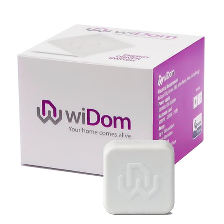
Product Picture


1 - Device Status
Controlling the relay by means of a single click on the external switch or on the integrated button.Size: 1 byte
Default: 1
Minimum: 0
Maximum: 0
Possible values
| From | To | Desription |
|---|---|---|
| 4 | 4 | IGNORE |
| 3 | 3 | OFF |
| 2 | 2 | ON |
| 1 | 1 | TOGGLE |
20 - Device status upon receipt of a Basic Set command
The final status achieved by the device when it receives a Basic Set command through the Z-Wave network.Size: 1 byte
Default: 0
Minimum: 0
Maximum: 0
Possible values
| From | To | Desription |
|---|---|---|
| 3 | 3 | IGNORE IF OFF |
| 4 | 4 | IGNORE |
| 1 | 1 | AS RECEIVED |
| 2 | 2 | IGNORE IF ON |
30 - Overcurrent level
Sets the current level above which the time spent above that level is measured.Size: 2 bytes
Default: 1250
Minimum: 0
Maximum: 0
Possible values
| From | To | Desription |
|---|---|---|
| 0 | 1250 | Overcurren level in hundredths of Amperes |
31 - Overcurrent time
Sets the time beyond which, in the case of overcurrent at a level higher than that established in parameter 30, an OverCurrent event occurs.Size: 2 bytes
Default: 10
Minimum: 0
Maximum: 0
Possible values
| From | To | Desription |
|---|---|---|
| 0 | 10800 | Time in seconds |
32 - Next State
Defines the next state of the device if an overcurrent event has occurred.Size: 1 byte
Default: 0
Minimum: 0
Maximum: 0
Possible values
| From | To | Desription |
|---|---|---|
| 2 | 2 | OFF |
| 0 | 0 | IGNORE |
| 3 | 3 | TOGGLE |
| 1 | 1 | ON |
33 - Meter Reset
Provides total operating time from last meter reset. When set to 0 it resets the cumulated values of energy and total operating time.Size: 4 bytes
Default: 1
Minimum: 0
Maximum: 0
Possible values
| From | To | Desription |
|---|---|---|
| 0 | 0 | RESET METER |
34 - Energy flow
Determines whether energy events are related to energy consumed or energy produced.Size: 1 byte
Default: 1
Minimum: 0
Maximum: 0
Possible values
| From | To | Desription |
|---|---|---|
| 1 | 1 | Consumed |
| 2 | 2 | Produced |
35 - UP Power Level
Sets the level of instantaneous power in Watts beyond which time of permanence above this level is calculated.Size: 2 bytes
Default: 3000
Minimum: 0
Maximum: 0
Possible values
| From | To | Desription |
|---|---|---|
| 0 | 3000 | UP Power level in Watt |
36 - UP Power Time
Sets the time in seconds beyond which, if instantaneous power remains at levels exceeding threshold defined by parameter 35, a UP Power event occurs.Size: 2 bytes
Default: 0
Minimum: 0
Maximum: 0
Possible values
| From | To | Desription |
|---|---|---|
| 0 | 10800 | UP Power Time in seconds |
38 - UP Power Associated
Defines the status of associated devices in the presence of a UP Power event.Size: 1 byte
Default: 0
Minimum: 0
Maximum: 0
Possible values
| From | To | Desription |
|---|---|---|
| 0 | 0 | OFF |
| 100 | 100 | ON |
| 1 | 99 | Dimming |
39 - DOWN Power Level
Sets the level of instantaneous power beyond which the time of permanence below this level is calculated.Size: 2 bytes
Default: 0
Minimum: 0
Maximum: 0
Possible values
| From | To | Desription |
|---|---|---|
| 0 | 11250 | DOWN Power Level in Watt |
40 - DOWN Power Time
Sets the time beyond which, if instantaneous power remains at levels below threshold defined by parameter 39, a DOWN Power event occurs.Size: 2 bytes
Default: 10
Minimum: 0
Maximum: 0
Possible values
| From | To | Desription |
|---|---|---|
| 0 | 10800 | DOWN Power Time in seconds |
41 - DOWN Power State
Defines the next state of the device in the case of a DOWN Power event occurring.Size: 1 byte
Default: 0
Minimum: 0
Maximum: 0
Possible values
| From | To | Desription |
|---|---|---|
| 1 | 1 | ON |
| 2 | 2 | OFF |
| 3 | 3 | TOGGLE |
| 0 | 0 | IGNORE |
42 - DOWN Power Associated
Defines the status of associated devices in the presence of a DOWN Power event.Size: 1 byte
Default: 0
Minimum: 0
Maximum: 0
Possible values
| From | To | Desription |
|---|---|---|
| 1 | 99 | Dimming |
| 0 | 0 | OFF |
| 255 | 255 | ON |
43 - Energy Level
Sets the energy level that once exceeded an Energy Limit event occurs.Size: 4 bytes
Default: 2000000
Minimum: 0
Maximum: 0
Possible values
| From | To | Desription |
|---|---|---|
| 0 | 2000000 | Energy Level in KWh |
44 - Energy Limit State
Defines the next state of the device in the case of an Energy Limit event occurring.Size: 1 byte
Default: 0
Minimum: 0
Maximum: 0
Possible values
| From | To | Desription |
|---|---|---|
| 0 | 0 | IGNORE |
| 1 | 1 | ON |
| 2 | 2 | OFF |
| 3 | 3 | TOGGLE |
45 - Variation Instantaneous Power
Defines the percentage variation of instantaneous power determining the sending of the report.Size: 1 byte
Default: 10
Minimum: 0
Maximum: 0
Possible values
| From | To | Desription |
|---|---|---|
| 1 | 100 | Power variation in percentage |
46 - Report Time Frequency
Defines the maximum time in minutes since the previous report beyond which an Instantaneous Power Report will still be sent.Size: 1 byte
Default: 10
Minimum: 0
Maximum: 0
Possible values
| From | To | Desription |
|---|---|---|
| 1 | 100 | Time in minutes |
48 - Nominal Voltage
Defines the nominal voltage value in tenths of volts. Together with parameter No. 49 this is used by the automatic notification system to send reports on variations of voltage.Size: 2 bytes
Default: 2300
Minimum: 0
Maximum: 0
Possible values
| From | To | Desription |
|---|---|---|
| 1100 | 2300 | Nominal Voltage in Volt |
49 - Fall in maximum voltage
Defines, as a percentage, the nominal value for permitted fall in maximum voltage.Size: 1 byte
Default: 10
Minimum: 0
Maximum: 0
Possible values
| From | To | Desription |
|---|---|---|
| 1 | 100 | percentage of voltage variation |
50 - Electric parameters subjected to automatic notification
Defines which electric parameters, other than power, will be subjected to automatic notification. The value to be set for this parameter must be calculated as the sum of values associated to the individual electric parameter.Size: 1 byte
Default: 30
Minimum: 0
Maximum: 0
Possible values
| From | To | Desription |
|---|---|---|
| 0 | 0 | Power |
| 2 | 2 | Energy |
| 4 | 4 | Voltage |
| 8 | 8 | Current |
| 16 | 16 | Power Factor |
| 32 | 32 | Multilevel Sensor: Power Report |
60 - Start-up status
Defines the status of the device following a restart.Size: 1 byte
Default: 3
Minimum: 0
Maximum: 0
Possible values
| From | To | Desription |
|---|---|---|
| 1 | 1 | ON |
| 3 | 3 | Status prior to restart |
| 2 | 2 | OFF |
61 - Configuration reset
Defines which parameters should be reset to default values.Size: 1 byte
Default: 4
Minimum: 0
Maximum: 0
Possible values
| From | To | Desription |
|---|---|---|
| 0 | 0 | FACTORY RESET |
| 1 | 1 | ASSOCIATIONS RESET |
| 2 | 2 | CONFIGURATIONS RESET |
| 4 | 4 | IGNORE |
62 - Type of external switch
Defines the type of external switch connected to the device.Size: 1 byte
Default: 4
Minimum: 0
Maximum: 0
Possible values
| From | To | Desription |
|---|---|---|
| 0 | 0 | IGNORE |
| 1 | 1 | BUTTON |
| 4 | 4 | AUTOMATIC RECOGNITION |
| 2 | 2 | SWITCH |
63 - Load control
Defines the load control mode.Size: 1 byte
Default: 1
Minimum: 0
Maximum: 0
Possible values
| From | To | Desription |
|---|---|---|
| 1 | 1 | DIRECT CONTROL |
| 3 | 3 | CONTROL BY MEANS OF A CONTACTOR WITH NORMALLY CLOSED COMMAND |
| 4 | 4 | AS AN EXTERNAL INDICATOR |
| 2 | 2 | CONTROL BY MEANS OF A CONTACTOR WITH NORMALLY OPEN COMMAND |
1. Put your system controller into inclusion mode by following the instructions provided by your controller manufacturer. 2. Press the push button (B) located on the top of the device once.""
1. Put your system controller into exclusion mode by following the instructions provided by your controller manufacturer. 2. Press the push button (B) located on the top of the device three time.""
Press the push button (B) located on the top of the device six consecutive times within one minute from system start-up. Please use this procedure only in the event that the primary controller is missing or otherwise inoperable.
Before invoke the firmware update from the controller press the push button (B) located on the top of the device four consecutive times.