FIBARO
FIBARO Motion Sensor
FGMS-001
Notification Sensor
1
ZM5202
6.51.06
0x010F (271)
0x0801 (2049)
0x2001 (8193)
ZC10-15100002
2015-10-05 12:29:12.6682
N/A
Enhanced 232 Slave
Reporting Sleeping Slave
The FIBARO Motion Sensor is highly advanced battery powered Z-Wave multi-sensor. Along with detecting motion the device measures a temperature and light intensity.
The FIBARO Motion Sensor is a highly advanced, ultra small multi-sensor. Motion Sensor honored with CES 2015 Innovation Awards and International Design Awards 2015. This tiny sensor has a built-in temperature sensor, light sensor and accelerometer. The eye of the sensor shines with user-defined colors to visually alert when detects motion and alarm. The Motion Sensor is completely wireless and mobile. • Plug and Play extremely easy installation on surface without drilling and cabling • Detects every motion and allows lighting controls and heating measuring • Possibility to Integrate with alarm or fire prevention system • Measures the temperature • Compatibles with any Z-Wave controller • Alarms of movement and temperature are signaled by LED diode blinking • Simple earthquake detector mode https://www.youtube.com/watch?v=R_I2p1Tq2QU
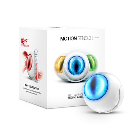
Product Picture


1 - MOTION SENSOR’S SENSITIVITY
The lower the value, the more sensitive the PIR sensor.Size: 2 bytes
Default: 15
Minimum: 0
Maximum: 0
Possible values
| From | To | Desription |
|---|---|---|
| 8 | 255 | The lower the value, the more sensitive the PIR sensor. |
2 - MOTION SENSOR’S BLIND TIME (INSENSITIVITY)
Period of time through which the PIR sensor is “blind” (insensitive) to motion. After this time period the PIR sensor will be again able to detect motion. The longer the insensitivity period, the longer the battery life. If the sensor is required to detect motion quickly, the time period may be shortened. The time of insensitivity should be shorter that the time period set in parameter 6 (cancellation delay).Size: 1 byte
Default: 15
Minimum: 0
Maximum: 0
Possible values
| From | To | Desription |
|---|---|---|
| 0 | 15 | 0,5 - 8 seconds. Formula to calculate the time: time [s] = 0.5 x (value + 1). |
3 - PIR sensor’s “PULSE COUNTER”
Sets the number of moves required for the PIR sensor to report motion. The higher the value, the less sensitive the PIR sensor. It’s not recommended to modify this parameter settings.Size: 1 byte
Default: 1
Minimum: 0
Maximum: 0
Possible values
| From | To | Desription |
|---|---|---|
| 0 | 3 | 1 - 4 pulses. Formula to calculate the number of pulses: pulses = (value + 1). |
4 - PIR sensor’s “WINDOW TIME”
Period of time during which the number of moves set in parameter 3 must be detected in order for the PIR sensor to report motion. The higher the value, the more sensitive the PIR sensor. It’s not recommended to modify this parameter setting.Size: 1 byte
Default: 2
Minimum: 0
Maximum: 0
Possible values
| From | To | Desription |
|---|---|---|
| 0 | 3 | Formula to calculate the time: time [s] = 4 x (value + 1). |
6 - MOTION ALARM CANCELLATION DELAY
Motion alarm will be cancelled in the main controller and the associated devices after the period of time set in this parameter. Any motion detected during the cancellation delay time countdown will result in the countdown being restarted. In case of small values, below 10 seconds, the value of parameter 2 must be modified (PIR sensor’s “Blind Time”).Size: 2 bytes
Default: 30
Minimum: 0
Maximum: 0
Possible values
| From | To | Desription |
|---|---|---|
| 1 | 32767 | seconds |
8 - PIR SENSOR OPERATING MODE
The parameter determines the part of day in which the PIR sensor will be active. This parameter influences only the motion reports and associations. Tamper, light intensity and temperature measurements will be still active, regardless of this parameter settings.Size: 1 byte
Default: 0
Minimum: 0
Maximum: 0
Possible values
| From | To | Desription |
|---|---|---|
| 0 | 0 | PIR sensor always active |
| 1 | 1 | PIR sensor active during the day only |
| 2 | 2 | PIR sensor active during the night only |
9 - NIGHT / DAY
The parameter defines the difference between night and day, in terms of light intensity, used in parameter 8.Size: 2 bytes
Default: 200
Minimum: 0
Maximum: 0
Possible values
| From | To | Desription |
|---|---|---|
| 1 | 32767 | lux |
12 - BASIC COMMAND CLASS FRAMES CONFIGURATION
The parameter determines the command frames sent in 2-nd association group, assigned to PIR sensor. Values of BASIC ON and BASIC OFF command frames may be modified by dedicated parameters (14 and 16).Size: 1 byte
Default: 0
Minimum: 0
Maximum: 0
Possible values
| From | To | Desription |
|---|---|---|
| 0 | 0 | BASIC ON and OFF command frames sent in Basic Command Class. |
| 1 | 1 | Only the BASIC ON command frame sent in Basic Command Class. |
| 2 | 2 | Only the BASIC OFF command frame sent in Basic Command Class. |
14 - BASIC ON command frame value
The command frame sent at the moment of motion detection. Further motion detections, during the cancellation time, will not result in sending the association.Size: 2 bytes
Default: 255
Minimum: 0
Maximum: 0
Possible values
| From | To | Desription |
|---|---|---|
| 0 | 255 | The value other than 0 allows to turn ON an associated device. In case of the Dimmer, the value of 255 means turning ON at the last memorized state, e.g. the Dimmer turned ON at 30% and turned OFF using the value of 255, and then turned OFF, will be turned ON at 30%, i.e. the last memorized state. |
16 - BASIC OFF command frame value
The command frame sent at the moment of motion alarm cancellation, after cancellation delay time specified in parameter 6.Size: 2 bytes
Default: 0
Minimum: 0
Maximum: 0
Possible values
| From | To | Desription |
|---|---|---|
| 0 | 255 | The value of 0 allows to turn a device OFF while the value of 255 allows to turn ON a device. In case of the Dimmer, the value of 255 means turning ON at the last memorized state, e.g. the Dimmer turned ON at 30% and turned OFF using the value of 255, and then turned OFF, will be turned ON at 30%, i.e. the last memorized state. |
18 - ASSOCIATIONS IN Z-WAVE NETWORK SECURITY MODE
This parameter defines how commands are sent in specified association groups: as secure or non-secure. Parameter is active only in Z-Wave network security mode. It doesn’t apply to 1st Lifeline group. Parameter values may be combined, e.g. 1+2=3 means that 2nd & 3rd group are sent as secure.Size: 1 byte
Default: 15
Minimum: 0
Maximum: 0
Possible values
| From | To | Desription |
|---|---|---|
| 0 | 0 | All groups sent as non-secure |
| 1 | 1 | 2nd group sent as secure |
| 2 | 2 | 3rd group sent as secure |
| 4 | 4 | 4th group sent as secure |
| 8 | 8 | 5th group sent as secure |
20 - TAMPER SENSITIVITY
The parameter determines the changes in forces acting on the Fibaro Motion Sensor resulting in tamper alarm being reported - g-force acceleration.Size: 1 byte
Default: 20
Minimum: 0
Maximum: 0
Possible values
| From | To | Desription |
|---|---|---|
| 1 | 121 | 0,08 - 2g; multiply by 0,016g |
| 0 | 0 | tamper inactive |
22 - TAMPER ALARM CANCELLATION DELAY
Time period after which a tamper alarm will be cancelled. Another tampering detected during the countdown to cancellation will not extend the delay.Size: 2 bytes
Default: 30
Minimum: 0
Maximum: 0
Possible values
| From | To | Desription |
|---|---|---|
| 1 | 32767 | seconds |
24 - TAMPER OPERATING MODES
The parameter determines the behaviour of tamper alarm and how it reports. It is an advanced feature serving much more functions than just detection of tampering.Size: 1 byte
Default: 0
Minimum: 0
Maximum: 0
Possible values
| From | To | Desription |
|---|---|---|
| 0 | 0 | Only tamper (default). |
| 1 | 1 | Tamper and earthquake detector. Function may be used as a simple seismograph. Two reports including the strength of shock are always sent. First, right after the detection and second (value=0) after tamper alarm cancellation delay time. |
| 2 | 2 | Tamper and orientation in space. Three reports are sent right after tamper alarm cancellation delay time. |
25 - TAMPER CANCELLATION REPORTS
Size: 1 byte
Default: 1
Minimum: 0
Maximum: 0
Possible values
| From | To | Desription |
|---|---|---|
| 0 | 0 | Do not send tamper cancellation report. |
| 1 | 1 | Send tamper cancellation report. |
28 - TAMPER ALARM BROADCAST MODE
The parameter determines whether the tamper alarm frame will or will not be sent in broadcast mode. Alarm frames sent in broadcast mode can be received by all of the devices within communication range (if they accept such frames). When Fibaro Motion Sensor is operating in protected mode (secure mode), the value should remain default. Device operating in protected mode doesn’t send frames in broadcast mode.Size: 1 byte
Default: 0
Minimum: 0
Maximum: 0
Possible values
| From | To | Desription |
|---|---|---|
| 0 | 0 | Tamper alarm reported to association groups. |
| 1 | 1 | Tamper alarm reported in broadcast mode to 3rd association group. |
29 - TAMPER ALARM BROADCAST MODE
The parameter determines whether the tamper alarm frame will or will not be sent in broadcast mode. Alarm frames sent in broadcast mode may be received by all of the devices within communication range (if they accept such frames). When Fibaro Motion Sensor is running in protected mode (secure mode), the value should remain default. Device operating in protected mode do not send frames in broadcast mode.Size: 1 byte
Default: 0
Minimum: 0
Maximum: 0
Possible values
| From | To | Desription |
|---|---|---|
| 0 | 0 | Tamper alarm reported to association groups. |
| 1 | 1 | Tamper alarm reported in broadcast mode to 5th association group. |
40 - ILLUMINATION REPORT THRESHOLD
The parameter determines the change in light intensity level resulting in illumination report being sent to the main controller.Size: 2 bytes
Default: 200
Minimum: 0
Maximum: 0
Possible values
| From | To | Desription |
|---|---|---|
| 0 | 0 | Reports are not sent. |
| 1 | 32767 | lux |
42 - ILLUMINATION REPORTS INTERVAL
Time interval between consecutive illumination reports. The reports are sent even if there are no changes in the light intensity. CAUTION: Frequent reports will shorten the battery life. Parameter value under 5 may result in blocking the temperature reports.Size: 2 bytes
Default: 3600
Minimum: 0
Maximum: 0
Possible values
| From | To | Desription |
|---|---|---|
| 1 | 32767 | seconds |
| 0 | 0 | no reports |
60 - TEMPERATURE REPORT THRESHOLD
The parameter determines the change in level of temperature resulting in temperature report being sent to the main controller.Size: 2 bytes
Default: 10
Minimum: 0
Maximum: 0
Possible values
| From | To | Desription |
|---|---|---|
| 1 | 255 | 0,1-25,5 degrees Celsius |
| 0 | 0 | reports are not sent |
62 - INTERVAL OF TEMPERATURE MEASURING
The parameter determines how often the temperature will be measured. The shorter the time, the more frequently the temperature will be measured, but the battery life will shorten. CAUTION: When parameter value is set to 0, the temperature measurements may be performed at the device wake-up.Size: 2 bytes
Default: 900
Minimum: 0
Maximum: 0
Possible values
| From | To | Desription |
|---|---|---|
| 1 | 32767 | seconds |
| 0 | 0 | temperature will not be measured |
64 - TEMPERATURE REPORTS INTERVAL
The parameter determines how often the temperature reports will be sent to the main controller. CAUTION: Frequent reports will shorten the battery life. Parameter value under 5 may result in blocking the illumination reports.Size: 2 bytes
Default: 0
Minimum: 0
Maximum: 0
Possible values
| From | To | Desription |
|---|---|---|
| 1 | 32767 | seconds |
| 0 | 0 | no reports |
66 - TEMPERATURE OFFSET
The value to be added to the actual temperature, measured by the sensor (temperature compensation).Size: 2 bytes
Default: 0
Minimum: 0
Maximum: 0
Possible values
| From | To | Desription |
|---|---|---|
| -1000 | 1000 | degrees Celsius |
80 - LED SIGNALING MODE
The parameter determines the way in which LED diode behaves after motion has been detected.Size: 1 byte
Default: 10
Minimum: 0
Maximum: 0
Possible values
| From | To | Desription |
|---|---|---|
| 1 | 9 | Single long blink at the moment of reporting motion. No other motion will be indicated until alarm is cancelled. |
| 10 | 18 | Single long blink at the moment of reporting motion and one short blink each time the motion is detected again. |
| 19 | 26 | Single long blink at the moment of reporting motion and two short blinks each time the motion is detected again. |
| 0 | 0 | LED inactive |
| 1 | 1 | LED colour depends on the temperature. Set by parameters 86 and 87. |
| 2 | 2 | Flashlight mode - LED glows in white for 10 seconds. |
| 3 | 3 | White |
| 4 | 4 | Red |
| 5 | 5 | Green |
| 6 | 6 | Blue |
| 7 | 7 | Yellow |
| 8 | 8 | Cyan |
| 9 | 9 | Magenta |
| 10 | 10 | LED colour depends on the temperature. Set by parameters 86 and 87. |
| 11 | 11 | Flashlight mode - LED glows in white through 10 sec. Each next detected motion extends the glowing by next 10 seconds. |
| 12 | 12 | White |
| 13 | 13 | Red |
| 14 | 14 | Green |
| 15 | 15 | Blue |
| 16 | 16 | Yellow |
| 17 | 17 | Cyan |
| 18 | 18 | Magenta |
| 19 | 19 | LED colour depends on the temperature. Set by parameters 86 and 87. |
| 20 | 20 | White |
| 21 | 21 | Red |
| 22 | 22 | Green |
| 23 | 23 | Blue |
| 24 | 24 | Yellow |
| 25 | 25 | Cyan |
| 26 | 26 | Magenta |
81 - LED BRIGHTNESS
The parameter determines the brightness of LED when indicating motion.Size: 1 byte
Default: 50
Minimum: 0
Maximum: 0
Possible values
| From | To | Desription |
|---|---|---|
| 1 | 100 | % |
| 0 | 0 | Brightness determined by the ambient lighting - see parameters 82 and 83. |
82 - AMBIENT ILLUMINATION LEVEL BELOW WHICH LED BRIGHTNESS IS SET TO 1%
The parameter is relevant only when the parameter 81 is set to 0.Size: 2 bytes
Default: 100
Minimum: 0
Maximum: 0
Possible values
| From | To | Desription |
|---|---|---|
| 0 | 32767 | lux |
83 - AMBIENT ILLUMINATION LEVEL ABOVE WHICH LED BRIGHTNESS IS SET TO 100%
The parameter is relevant only when the parameter 81 is set to 0. Available settings: CAUTION: The value of parameter 83 must be higher than the value of parameter 82.Size: 2 bytes
Default: 1000
Minimum: 0
Maximum: 0
Possible values
| From | To | Desription |
|---|---|---|
| 1 | 32767 | Parameter 82 value to 32767 (1-32767 lux). |
86 - MINIMUM TEMPERATURE RESULTING IN BLUE LED ILLUMINATION
This parameter is relevant only when parameter 80 has been properly configured.Size: 2 bytes
Default: 18
Minimum: 0
Maximum: 0
Possible values
| From | To | Desription |
|---|---|---|
| 0 | 255 | 0 to parameter 87 value (0-255[C]). |
87 - MAXIMUM TEMPERATURE RESULTING IN RED LED ILLUMINATION
This parameter is relevant only when parameter 80 has been properly configured. CAUTION: The value of parameter 87 must be higher than the value of parameter 86.Size: 2 bytes
Default: 28
Minimum: 0
Maximum: 0
Possible values
| From | To | Desription |
|---|---|---|
| 0 | 255 | Parameter 86 value to 255 (0-255[C]). |
89 - LED INDICATING TAMPER ALARM
Indicating mode resembles a police car (white, red and blue).Size: 1 byte
Default: 1
Minimum: 0
Maximum: 0
Possible values
| From | To | Desription |
|---|---|---|
| 0 | 0 | LED does not indicate tamper alarm. |
| 1 | 1 | LED indicates tamper alarm. |
The Fibaro Motion Sensor can be included into the Z-Wave network by using the B-button. 1) Open the sensor’s casing by turning the cover counter-clockwise. Enclosure lock is marked with a dot. 2) Unlock battery by removing “I'm ready” stripe. 3) Make sure the device is located within the direct range of the main controller. 4) Set the main controller into learning mode (see main controller’s operating manual). 5) Quickly, triple click the B-button - LED diode will glow blue to confirm setting into learning mode. 6) Fibaro Motion Sensor will be detected and included into the Z-Wave network. Wait for the main controller to configure the sensor. 7) If necessary, wake up the Motion Sensor by clicking the B-button. 8) Close the sensor’s casing and install the device in desired place. https://www.youtube.com/watch?v=TRl56z5tazc&list=PLdQIrrMY01UCp5cirju9sOjTu6JjuCaf2&index=1
1) Open the sensor’s casing by turning the cover counter-clockwise. 2) Place the Motion Sensor within the direct range of your Z-Wave controller. 3) Set the main controller into remove mode (see the controller’s manual). 4) Quickly, three times press the B-button located inside Fibaro Motion Sensor’s casing – visual indicator will glow blue. 5) Wait for the removing process to end. 6) Successful removing will be confirmed by the Z-Wave controller.
The Motion Sensor will wake up at a defined time interval and will ALWAYS try to communicate with the main controller. There is a possibility to wake up the device manually by clicking the B-button. https://www.youtube.com/watch?v=oQ8PsUWoxzc&list=PLdQIrrMY01UCp5cirju9sOjTu6JjuCaf2&index=3
Please use this procedure only in the event that the system primary controller is missing or otherwise inoperable. To reset the device: 1) Make sure the battery works and is in place. 2) Press and hold the B-button for 4-6 seconds until the LED glows yellow signaling the 2nd option of the menu mode. 3) Release the B-button. 4) Again, press the B-button briefly. Successful reset will be confirmed with the LED changing colour to red and fading. https://www.youtube.com/watch?v=cfY-acPN3j0&list=PLdQIrrMY01UCp5cirju9sOjTu6JjuCaf2&index=2 For more information please check the user's manuals.