FIBARO
FIBARO Dimmer 2
FGD-212
Light Dimmer Switch
2
ZM5202
6.51.06
0x010F (271)
0x0102 (258)
0x2000 (8192)
ZC10-16010009
2016-01-14 16:48:02.148
N/A
Enhanced 232 Slave
Always On Slave
Dimmer 2 is a new, improved universal dimming module. Dimmer 2 allows remote control over any source of light. It significantly extends the lifespan of the bulbs and reduces the electricity use.
FIBARO Dimmer 2 is a device designed to control various types of light sources in 2 or 3-wire connection. The device can switch or dim connected light source remotely using Z-Wave wireless protocol or through the wall switch connected directly to it. Dimmer 2 is equipped with a smart algorithm of light source detection which makes configuration easier and ensures high compatibility of the device. It may be used as a switch with non-dimmable light sources in 3-wire connection. Active power and energy consumption allows to monitor and reduce electricity bills. Dimmer 2 is compatible with any Z-Wave or Z-Wave Plus Controller. As a dimmer it operates under the following loads: • 230V operated conventional incandescent and halogen light sources • ELV electronic transformers (12V operated halogen lamps and dimmable LED bulbs) • MLV ferromagnetic transformers with 12V operated halogen lamps • dimmable LED bulbs • dimmable compact fluorescent CFL tube lamps • supported dimmable light sources with minimal power of 5VA (power factor > 0.5) using FIBARO Bypass FGB-002 Without dimming function it may work with: • compact fluorescent lamps • fluorescent tube lamps with electronic ballast • LED bulbs (power factor > 0.7) • supported light sources with minimal power of 5VA (power factor > 0.5) using FIBARO Bypass FGB-002
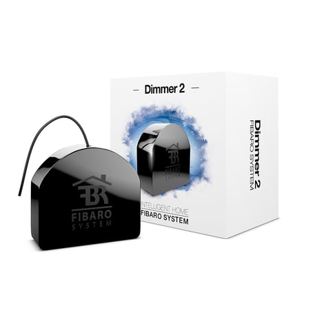
Product Picture


1 - Minimum brightness level
The parameter is set automatically during the calibration process. The parameter can be changed manually after the calibration.Size: 1 byte
Default: 1
Minimum: 0
Maximum: 0
Possible values
| From | To | Desription |
|---|---|---|
| 1 | 98 | percentage level of brightness |
| 0 | 0 |
2 - Maximum brightness level
The parameter is set automatically during the calibration process. The parameter can be changed manually after the calibration. CAUTION: The maximum brightness level (parameter 2) must be greater than the minimum brightness level (parameter 1).Size: 1 byte
Default: 99
Minimum: 0
Maximum: 0
Possible values
| From | To | Desription |
|---|---|---|
| 2 | 99 | percentage level of brightness |
3 - Incandescence level of dimmable compact fluorescent lamps
Virtual value set as a percentage level between parameters MIN (1%) and MAX. (99%). The Dimmer 2 will set to this value after first switch on. It is required for warming up and switching dimmable compact fluorescent lamps and certain types of light sources.Size: 1 byte
Default: 1
Minimum: 0
Maximum: 0
Possible values
| From | To | Desription |
|---|---|---|
| 1 | 99 | percentage level of brightness |
4 - Incandescence time of dimmable compact fluorescent lamps
This parameter determines the time required for switching compact fluorescent lamps and certain types of light sources. Setting this parameter to 0 will disable the incandescence functionality.Size: 2 bytes
Default: 0
Minimum: 0
Maximum: 0
Possible values
| From | To | Desription |
|---|---|---|
| 0 | 255 | (0-25.5s) |
5 - Automatic control - dimming step size
This parameter defines the percentage value of dimming step during the automatic control. NOTE: Automatic control is performed through: single push-button click; double push-button click; Z-Wave control frames.Size: 1 byte
Default: 1
Minimum: 0
Maximum: 0
Possible values
| From | To | Desription |
|---|---|---|
| 1 | 99 | dimming step percentage value |
6 - Automatic control - time of a dimming step
This parameter defines the time of single dimming step set in parameter 5 during the automatic control. NOTE: Automatic control is performed through: single push-button click; double push-button click; Z-Wave control frames.Size: 2 bytes
Default: 1
Minimum: 0
Maximum: 0
Possible values
| From | To | Desription |
|---|---|---|
| 0 | 255 | (0-2.55s, in 10ms steps) |
7 - Manual control - dimming step size
This parameter defines the percentage value of dimming step during the manual control. NOTE: Manual control is performed through holding the push-button.Size: 1 byte
Default: 1
Minimum: 0
Maximum: 0
Possible values
| From | To | Desription |
|---|---|---|
| 1 | 99 | dimming step percentage value |
8 - Manual control - time of a dimming step
This parameter defines the time of single dimming step set in parameter 7 during the manual control.Size: 2 bytes
Default: 5
Minimum: 0
Maximum: 0
Possible values
| From | To | Desription |
|---|---|---|
| 0 | 255 | (0-2.55s, in 10ms steps) |
9 - State of the device after a power failure
The Dimmer 2 will return to the last state before power failure.Size: 1 byte
Default: 1
Minimum: 0
Maximum: 0
Possible values
| From | To | Desription |
|---|---|---|
| 0 | 0 | the Dimmer 2 does not save the state before a power failure, it returns to „off” position |
| 1 | 1 | the Dimmer 2 restores its state before power failure |
10 - Timer functionality (auto - off)
This parameter allows to automatically switch off the device after specified time from switching on the light source. It may be useful when the Dimmer 2 is installed in the stairway.Size: 2 bytes
Default: 0
Minimum: 0
Maximum: 0
Possible values
| From | To | Desription |
|---|---|---|
| 0 | 0 | Function disabled |
| 1 | 32767 | time to turn off measured in seconds (1s-9.1h) |
11 - ALL ON/ALL OFF function
Parameter allows for activation/deactivation of Z-Wave commands enabling/disabling all devices located in direct range of the main controller.Size: 2 bytes
Default: 255
Minimum: 0
Maximum: 0
Possible values
| From | To | Desription |
|---|---|---|
| 0 | 0 | ALL ON not active, ALL OFF not active |
| 1 | 1 | ALL ON not active, ALL OFF active |
| 2 | 2 | ALL ON active, ALL OFF not active |
| 255 | 255 | ALL ON active, ALL OFF active |
13 - Force auto-calibration
Changing value of this parameter will force the calibration process. During the calibration parameter is set to 1 or 2 and switched to 0 upon completion.Size: 1 byte
Default: 0
Minimum: 0
Maximum: 0
Possible values
| From | To | Desription |
|---|---|---|
| 0 | 0 | readout |
| 1 | 1 | force auto-calibration of the load without FIBARO Bypass 2 |
| 2 | 2 | force auto-calibration of the load with FIBARO Bypass 2 |
14 - Auto-calibration status
(read-only parameter) This parameter determines operating mode of the Dimmer 2 (automatic/manual settings).Size: 1 byte
Default: 0
Minimum: 0
Maximum: 0
Possible values
| From | To | Desription |
|---|---|---|
| 0 | 0 | calibration procedure not performed or Dimmer 2 operates on manual settings |
| 1 | 1 | Dimmer 2 operates on auto-calibration settings |
15 - Burnt out bulb detection
Function based on the sudden power variation of a specific value, interpreted as a LOAD ERROR. CAUTION: Parameter 15 is relevant only when parameter 58 is set to 0 and the control mode is consistent with the mode set during the calibration process (parameter 30).Size: 1 byte
Default: 30
Minimum: 0
Maximum: 0
Possible values
| From | To | Desription |
|---|---|---|
| 0 | 0 | function disabled |
| 1 | 99 | percentage value of power variation, compared to standard power consumption, measured during the calibration procedure (to be interpreted as load error/burnt out bulb) |
16 - Time delay of a burnt out bulb (parameter 15) or overload (parameter 39) detection
Time of delay (in seconds) for power variation detection, interpreted as a LOAD ERROR or OVERLOAD detection (too much power connected to the Dimmer 2).Size: 2 bytes
Default: 5
Minimum: 0
Maximum: 0
Possible values
| From | To | Desription |
|---|---|---|
| 0 | 0 | detection of a burnt out bulb disabled |
| 1 | 255 | delay time in seconds |
19 - Forced switch on brightness level
If the parameter is active, switching on the Dimmer 2 (S1 single click) will always set this brightness level.Size: 1 byte
Default: 0
Minimum: 0
Maximum: 0
Possible values
| From | To | Desription |
|---|---|---|
| 0 | 0 | function disabled |
| 1 | 99 | percentage level of brightness |
20 - Switch type
Choose between momentary, toggle and roller blind switch.Size: 1 byte
Default: 0
Minimum: 0
Maximum: 0
Possible values
| From | To | Desription |
|---|---|---|
| 0 | 0 | momentary switch |
| 1 | 1 | toggle switch |
| 2 | 2 | roller blind switch - two switches operate the Dimmer 2 (S1 to brighten, S2 to dim) |
21 - The value sent to associated devices on single click
This parameter defines the value sent to devices associated with Dimmer 2 after its enabling.Size: 1 byte
Default: 0
Minimum: 0
Maximum: 0
Possible values
| From | To | Desription |
|---|---|---|
| 0 | 0 | 0xFF value is sent, which will set associated devices to their last saved state |
| 1 | 1 | current Dimmer 2 state is sent, which will synchronize brightness level of associated devices (other dimmers for example) |
22 - Assign toggle switch status to the device status
By default each change of toggle switch position results in action of Dimmer 2 (switch on/off) regardless the physical connection of conntacts.Size: 1 byte
Default: 0
Minimum: 0
Maximum: 0
Possible values
| From | To | Desription |
|---|---|---|
| 0 | 0 | device changes status on switch status change |
| 1 | 1 | device status is synchronized with switch status |
23 - Double click option - set the brightness level to MAX
Sets reaction for double click - brightness level to MAX: 0 - double click disabled 1 - double click enabled.Size: 1 byte
Default: 1
Minimum: 0
Maximum: 0
Possible values
| From | To | Desription |
|---|---|---|
| 0 | 0 | double click disabled |
| 1 | 1 | double click enabled |
24 - Command frames sent in 2nd and 3rd association groups (S1 associations)
Parameter determines, which actions will not result in sending frames to association groups. NOTE: Parameter 24 values may be combined, e.g. 1+2=3 means that associations on switching ON or OFF the Dimmer 2 (single click) will not be sent.Size: 1 byte
Default: 0
Minimum: 0
Maximum: 0
Possible values
| From | To | Desription |
|---|---|---|
| 0 | 0 | all actions send to association groups |
| 1 | 1 | do not send when switching ON (single click) |
| 2 | 2 | do not send when switching OFF (single click) |
| 4 | 4 | do not send when changing dimming level (holding and releasing) |
| 8 | 8 | do not send on double click |
| 16 | 16 | send 0xFF value on double click |
25 - Command frames sent in 4th and 5th association groups (S2 associations)
Parameter determines, which actions will not result in sending frames to association groups. NOTE: Parameter 25 values may be combined, e.g. 1+2=3 means that associations on switching ON or OFF the Dimmer 2 (single click) will not be sent.Size: 1 byte
Default: 0
Minimum: 0
Maximum: 0
Possible values
| From | To | Desription |
|---|---|---|
| 0 | 0 | all actions send to association groups |
| 1 | 1 | do not send when switching ON (single click) |
| 2 | 2 | do not send when switching OFF (single click) |
| 4 | 4 | do not send when changing dimming level (holding and releasing) |
| 8 | 8 | do not send on double click |
| 16 | 16 | send 0xFF value on double click |
26 - The function of 3-way switch
Switch no. 2 controls the Dimmer 2 additionally (in 3-way switch mode). Function disabled for parameter 20 set to 2 (roller blind switch).Size: 1 byte
Default: 0
Minimum: 0
Maximum: 0
Possible values
| From | To | Desription |
|---|---|---|
| 0 | 0 | 3-way switch function for S2 disabled |
| 1 | 1 | 3-way switch function for S2 enabled |
27 - Associations in Z-Wave network security mode
This parameter defines how commands are sent in specified association groups: as secure or non-secure. Parameter is active only in Z-Wave network security mode. It does not apply to 1st Lifeline group. NOTE: Parameter 27 values may be combined, e.g. 1+2=3 means that 2nd & 3rd group are sent as secure.Size: 1 byte
Default: 15
Minimum: 0
Maximum: 0
Possible values
| From | To | Desription |
|---|---|---|
| 0 | 0 | all groups (II-V) sent as non-secure |
| 1 | 1 | 2nd group sent as secure |
| 2 | 2 | 3rd group sent as secure |
| 4 | 4 | 4th group sent as secure |
| 8 | 8 | 5th group sent as secure |
| 15 | 15 | all groups (II-V) sent as secure |
28 - Scene activation functionality
SCENE ID depends on the switch type configurations. NOTE: Enabling scene activation functionality may cause slight delay in response to external switches and sending associations. For more details check the manual.Size: 1 byte
Default: 0
Minimum: 0
Maximum: 0
Possible values
| From | To | Desription |
|---|---|---|
| 0 | 0 | functionality deactivated |
| 1 | 1 | functionality activated |
29 - Switch functionality of S1 and S2
This parameter allows for switching the role of keys connected to S1 and S2 without changes in connection.Size: 1 byte
Default: 0
Minimum: 0
Maximum: 0
Possible values
| From | To | Desription |
|---|---|---|
| 0 | 0 | standard mode |
| 1 | 1 | S1 operates as S2, S2 operates as S1 |
30 - Load control mode
This parameter allows to set the desired load control mode. The device automatically adjusts correct control mode, but the installer may force its change using this parameter. Forced auto-calibration will set this parameter’s value to 2. CAUTION: Modifications of parameters in GROUP 30 should be performed only by a qualified installer.Size: 1 byte
Default: 2
Minimum: 0
Maximum: 0
Possible values
| From | To | Desription |
|---|---|---|
| 0 | 0 | forced leading edge control |
| 1 | 1 | forced trailing edge control |
| 2 | 2 | control mode selected automatically (based on auto-calibration) |
31 - Load control mode recognized during auto-calibration
Read only parameter.Size: 1 byte
Default: 0
Minimum: 0
Maximum: 0
Possible values
| From | To | Desription |
|---|---|---|
| 0 | 0 | leading edge |
| 1 | 1 | trailing edge |
32 - On/Off mode
This mode is necessary while connecting non-dimmable light sources. Setting this parameter to 1 automatically ignores brightening/dimming time settings. Forced auto-calibration will set this parameter’s value to 2.Size: 1 byte
Default: 2
Minimum: 0
Maximum: 0
Possible values
| From | To | Desription |
|---|---|---|
| 0 | 0 | on/off mode disabled (dimming is possible) |
| 1 | 1 | on/off mode enabled (dimming is not possible) |
| 2 | 2 | mode selected automatically |
33 - Dimmability of the load
This read only parameter contains an information about possibility of dimming the load detected during calibration procedure.Size: 1 byte
Default: 0
Minimum: 0
Maximum: 0
Possible values
| From | To | Desription |
|---|---|---|
| 0 | 0 | Load recognized as dimmable |
| 1 | 1 | Load recognized as non-dimmable |
34 - Soft-Start functionality
Time required to warm up the filament of halogen bulb.Size: 1 byte
Default: 1
Minimum: 0
Maximum: 0
Possible values
| From | To | Desription |
|---|---|---|
| 0 | 0 | no soft-start |
| 1 | 1 | short soft-start (0.1s) |
| 2 | 2 | long soft-start (0.5s) |
35 - Auto-calibration after power on
This parameter determines the trigger of auto-calibration procedure, e.g. power on, load error, etc.Size: 1 byte
Default: 1
Minimum: 0
Maximum: 0
Possible values
| From | To | Desription |
|---|---|---|
| 0 | 0 | No auto-calibration of the load after power on |
| 1 | 1 | Auto-calibration performed after first power on |
| 2 | 2 | Auto-calibration performed after each power on |
| 3 | 3 | Auto-calibration performed after first power on or after each LOAD ERROR alarm (no load, load failure, burnt out bulb), if parameter 37 is set to 1 also after alarms: SURGE (Dimmer 2 output overvoltage) and OVERCURRENT (Dimmer 2 output overcurrent) |
| 4 | 4 | Auto-calibration performed after each power on or after each LOAD ERROR alarm (no load, load failure, burnt out bulb), if parameter 37 is set to 1 also after alarms: SURGE (Dimmer 2 output overvoltage) and OVERCURRENT (Dimmer 2 output overcurrent) |
37 - Behaviour of the Dimmer 2 after OVERCURRENT or SURGE
Occuring of errors related to surge or overcurrent results in turning off the output to prevent possible malfunction. By default the device performs three attempts to turn on the load (useful in case of momentary, short failures of the power supply).Size: 1 byte
Default: 1
Minimum: 0
Maximum: 0
Possible values
| From | To | Desription |
|---|---|---|
| 0 | 0 | device permanently disabled until re-enabling by command or external switch |
| 1 | 1 | three attempts to turn on the load |
39 - Power limit - OVERLOAD
Reaching the defined value will result in turning off the load. Additional apparent power limit of 350VA is active by default. NOTE: Parameter 39 is relevant only when parameter 58 is set to 0.Size: 2 bytes
Default: 250
Minimum: 0
Maximum: 0
Possible values
| From | To | Desription |
|---|---|---|
| 0 | 0 | functionality disabled |
| 1 | 350 | (1-350W) |
40 - Response to General Purpose Alarm
Sets response to General Purpose Alarm: 0 - No reaction 1 - Turn on the load 2 - Turn off the load 3 - Load blinkingSize: 1 byte
Default: 3
Minimum: 0
Maximum: 0
Possible values
| From | To | Desription |
|---|---|---|
| 0 | 0 | No reaction |
| 1 | 1 | Turn on the load |
| 2 | 2 | Turn off the load |
| 3 | 3 | Load blinking |
41 - Response to Water Flooding Alarm
Sets response to Water Flooding Alarm: 0 - No reaction 1 - Turn on the load 2 - Turn off the load 3 - Load blinking.Size: 1 byte
Default: 2
Minimum: 0
Maximum: 0
Possible values
| From | To | Desription |
|---|---|---|
| 0 | 0 | No reaction |
| 1 | 1 | Turn on the load |
| 2 | 2 | Turn off the load |
| 3 | 3 | Load blinking |
42 - Response to Smoke, CO or CO2 Alarm
Sets response to Smoke, CO or CO2 Alarm: 0 - No reaction 1 - Turn on the load 2- Turn off the load 3 - Load blinking.Size: 1 byte
Default: 3
Minimum: 0
Maximum: 0
Possible values
| From | To | Desription |
|---|---|---|
| 0 | 0 | No reaction |
| 1 | 1 | Turn on the load |
| 2 | 2 | Turn off the load |
| 3 | 3 | Load blinking |
43 - Response to Temperature Alarm
Sets response to Temperature Alarm: 0 - No reaction 1 - Turn on the load 2 - Turn off the load 3 - Load blinking.Size: 1 byte
Default: 1
Minimum: 0
Maximum: 0
Possible values
| From | To | Desription |
|---|---|---|
| 0 | 0 | No reaction |
| 1 | 1 | Turn on the load |
| 2 | 2 | Turn off the load |
| 3 | 3 | Load blinking |
44 - Time of alarm state
NOTE: Alarm state may be cancelled earlier, as a result of pressing the switch or sending the Z-Wave command frame.Size: 2 bytes
Default: 600
Minimum: 0
Maximum: 0
Possible values
| From | To | Desription |
|---|---|---|
| 1 | 32767 | (1-32767 seconds) |
45 - OVERLOAD alarm report
(load power consumption too high)Size: 1 byte
Default: 1
Minimum: 0
Maximum: 0
Possible values
| From | To | Desription |
|---|---|---|
| 0 | 0 | No reaction |
| 1 | 1 | Send an alarm frame |
46 - LOAD ERROR alarm report
(no load, load failure, burnt out bulb)Size: 1 byte
Default: 1
Minimum: 0
Maximum: 0
Possible values
| From | To | Desription |
|---|---|---|
| 0 | 0 | No reaction |
| 1 | 1 | Send an alarm frame |
47 - OVERCURRENT alarm report
(short circuit, burnt out bulb causing overcurrent)Size: 1 byte
Default: 1
Minimum: 0
Maximum: 0
Possible values
| From | To | Desription |
|---|---|---|
| 0 | 0 | No reaction |
| 1 | 1 | Send an alarm frame |
48 - SURGE alarm report
(Dimmer 2 output overvoltage)Size: 1 byte
Default: 1
Minimum: 0
Maximum: 0
Possible values
| From | To | Desription |
|---|---|---|
| 0 | 0 | No reaction |
| 1 | 1 | Send an alarm frame |
49 - OVERHEAT (critical temperature) and VOLTAGE DROP (low voltage) alarm report
Sets OVERHEAT (critical temperature) and VOLTAGE DROP (low voltage) alarm report: 0 - No reaction 1 - Send an alarm frame.Size: 1 byte
Default: 1
Minimum: 0
Maximum: 0
Possible values
| From | To | Desription |
|---|---|---|
| 0 | 0 | No reaction |
| 1 | 1 | Send an alarm frame |
50 - Active power reports
The parameter defines the power level change that will result in a new power report being sent. The value is a percentage of the previous report.Size: 1 byte
Default: 10
Minimum: 0
Maximum: 0
Possible values
| From | To | Desription |
|---|---|---|
| 0 | 0 | power reports disabled |
| 1 | 100 | (1-100%) power report threshold |
52 - Periodic active power and energy reports
Parameter 52 defines a time period between consecutive reports. Timer is reset and counted from zero after each report.Size: 2 bytes
Default: 3600
Minimum: 0
Maximum: 0
Possible values
| From | To | Desription |
|---|---|---|
| 0 | 0 | periodic reports disabled |
| 1 | 32767 | (1-32767 seconds) |
53 - Energy reports
Energy level change which will result in sending a new energy report.Size: 2 bytes
Default: 10
Minimum: 0
Maximum: 0
Possible values
| From | To | Desription |
|---|---|---|
| 0 | 0 | energy reports disabled |
| 1 | 255 | (0.01-2.55 kWh) report triggering threshold |
54 - Self-measurement
The Dimmer 2 may include active power and energy consumed by itself in reports sent to the main controller.Size: 1 byte
Default: 0
Minimum: 0
Maximum: 0
Possible values
| From | To | Desription |
|---|---|---|
| 0 | 0 | Self-measurement inactive |
| 1 | 1 | Self-measurement active |
58 - Method of calculating the active power
This parameter defines how to calculate active power. It is useful in a case of 2-wire connection with light sources other than resistive. NOTE: Parameter 58 is set to 0 after forced auto-calibration.Size: 1 byte
Default: 0
Minimum: 0
Maximum: 0
Possible values
| From | To | Desription |
|---|---|---|
| 0 | 0 | measurement based on the standard algorithm |
| 1 | 1 | approximation based on the calibration data |
| 2 | 2 | approximation based on the control angle |
59 - Approximated power at the maximum brightness level
This parameter determines the approximate value of the power that will be reported by the device at its maximum brightness level. NOTE: Parameter 59 works only when parameter 58 has a value other than 0.Size: 2 bytes
Default: 0
Minimum: 0
Maximum: 0
Possible values
| From | To | Desription |
|---|---|---|
| 0 | 500 | (0-500W) power consumed by the load at the maximum brightness level |
| 0 | 0 |
1) Switch off the mains voltage. 2) Open the wall switch box. 3) Connect the Dimmer in accordance with one of the diagrams attached in the manual. 4) Switch on the mains voltage. 5) Wait for the calibration process to end. Light may blink. The device will be switched off once the process is completed. 6) Set the main Z-Wave controller into learning mode. 7) Quickly, three times press the B-button or key connected to the S1 terminal. 8) Wait for the device to be included into the system. Successful inclusion will be confirmed by the controller. 9) Arrange the antenna and close the wall switch box.
1) Set the main Z-Wave controller into learning mode. 2) Quickly, three times press the B-button or key connected to the S1 terminal. 3) Wait for the device to be excluded from the system. Successful inclusion will be confirmed by the controller.
The Fibaro Dimmer 2 is powered with mains voltage so it is always awake.
1) Disconnect the power supply, remove the Dimmer from the wall switch box, than connect the power supply. 2) Locate the B-button on the housing. 3) Click and hold the B-button to enter the menu mode. 4) Release and click the B-button to choose ""Device reset"" option in the menu that is signaled with the yellow LED indicator colour. 5) After few seconds the device will be restarted, which is signaled with the red LED indicator colour and entering the calibration mode. Note! Resetting the device is not the recommended way of removing the device from the Z-Wave network. Use reset procedure only if the primary controller is missing or inoperable.
Active power and energy metering functionality Soft start function Memory of the last lighting level settings Z-Wave range tester LED diode