QUBINO
Qubino Flush 2 relays
ZMNHB
On/Off Power Switch
App: 5.0
ZM5202
6.51.06
0x0159 (345)
0x0002 (2)
0x0051 (81)
ZC10-15100010
2015-10-14 09:40:10.0178
N/A
Enhanced 232 Slave
Always On Slave
Module is used for switching on or off two electrical devices and measure power consumtion.
Flush 2 relays module is used for switching on or off two electrical devices (e.g. lights, fans, etc ...). The module can be controlled either through Z-Wave network or through the wall switches. The module is designed to be mounted inside a “flush mounting box”, hidden behind a traditional wall switch. Module measures power consumption of two electrical devices and supports connection of digital temperature sensor. It is designed to act as repeater in order to improve range and stability of Z-wave network.
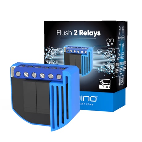
Product Picture


1 - Input 1 switch type
Input 1 switch typeSize: 1 byte
Default: 1
Minimum: 0
Maximum: 0
Possible values
| From | To | Desription |
|---|---|---|
| 0 | 0 | mono-stable switch type (push button) |
| 1 | 1 | bi-stable switch type |
2 - Input 2 switch type
Input 2 switch typeSize: 1 byte
Default: 1
Minimum: 0
Maximum: 0
Possible values
| From | To | Desription |
|---|---|---|
| 0 | 0 | mono-stable switch type (push button) |
| 1 | 1 | bi-stable switch type |
10 - Activate / deactivate functions ALL ON/ALL OFF
Activate / deactivate functions ALL ON/ALL OFF Flush 2 relays module responds to commands ALL ON / ALL OFF that may be sent by the main controller or by other controller belonging to the system.Size: 2 bytes
Default: 255
Minimum: 0
Maximum: 0
Possible values
| From | To | Desription |
|---|---|---|
| 255 | 255 | ALL ON active, ALL OFF active |
| 0 | 0 | ALL ON is not active ALL OFF is not active |
| 1 | 1 | ALL ON is not active ALL OFF active |
| 2 | 2 | ALL ON active ALL OFF is not active |
11 - Automatic turning off output Q1 after set time
When relay Q1 is ON it goes automatically OFF after time defined by this parameter. Timer is reset to zero each time the module receive ON command regardless from where it comes (push button, associated module, controller,..).Size: 2 bytes
Default: 0
Minimum: 0
Maximum: 0
Possible values
| From | To | Desription |
|---|---|---|
| 0 | 0 | Auto OFF disabled |
| 1 | 32535 | 1second (0,01s) – 32535 seconds (325,35s) Auto OFF enabled with define time, step is 1s or 10ms according to parameter nr.15 |
12 - Automatic turning on output Q1 after set time
When relay Q1 is OFF it goes automatically ON after time defined by this parameter. Timer is reset to zero each time the module receive OFF command regardless from where it comes (push button, associated module, controller,..).Size: 2 bytes
Default: 0
Minimum: 0
Maximum: 0
Possible values
| From | To | Desription |
|---|---|---|
| 0 | 0 | Auto ON disabled |
| 1 | 32535 | 1second (0,01s) – 32536 seconds (325,35s) Auto ON enabled with define time, step is 1s or 10ms according to parameter nr.15 |
13 - Automatic turning off output Q2 after set time
When relay Q2 is ON it goes automatically OFF after time defined by this parameter. Timer is reset to zero each time the module receive ON command regardless from where it comes (push button, associated module, controller,..).Size: 2 bytes
Default: 0
Minimum: 0
Maximum: 0
Possible values
| From | To | Desription |
|---|---|---|
| 0 | 0 | Auto OFF disabled |
| 1 | 32535 | 1second (0,01s) – 32535 seconds (325,35s) Auto OFF enabled with define time, step is 1s or 10ms according to parameter nr.15 |
14 - Automatic turning on output Q2 after set time
When relay Q2 is OFF it goes automatically ON after time defined by this parameter. Timer is reset to zero each time the module receive OFF command regardless from where it comes (push button, associated module, controller,..).Size: 2 bytes
Default: 0
Minimum: 0
Maximum: 0
Possible values
| From | To | Desription |
|---|---|---|
| 0 | 0 | Auto ON disabled |
| 1 | 32535 | 1second (0,01s) – 32536 seconds (325,35s) Auto ON enabled with define time, step is 1s or 10ms according to parameter nr.15 |
15 - Automatic turning off / on seconds or milliseconds selection
Automatic turning off / on seconds or milliseconds selection Note that parameter is valid for both outputs Q1, Q2 and is the same for turning off or on.Size: 1 byte
Default: 0
Minimum: 0
Maximum: 0
Possible values
| From | To | Desription |
|---|---|---|
| 0 | 0 | seconds selected |
| 1 | 1 | milliseconds selected |
30 - Saving the state of the relays Q1 and Q2 after a power failure
Saving the state of the relays Q1 and Q2 after a power failureSize: 1 byte
Default: 0
Minimum: 0
Maximum: 0
Possible values
| From | To | Desription |
|---|---|---|
| 0 | 0 | Flush 2 relays module saves its state before power failure (it returns to the last position saved before a power failure) |
| 1 | 1 | Flush 2 relays module does not save the state after a power failure, it returns to "off" position. |
40 - Power reporting in Watts on power change for Q1
Set value means percentage, set value from 0 – 100 = 0% - 100%.Size: 1 byte
Default: 10
Minimum: 0
Maximum: 0
Possible values
| From | To | Desription |
|---|---|---|
| 0 | 0 | Reporting Disabled |
| 1 | 100 | 1% - 100% Reporting enabled. Power report is send (push) only when actual power in Watts in real time changes for more than set percentage comparing to previous actual power in Watts, step is 1%. NOTE: if power changed is less than 1W, the report is not send (pushed), independent of percentage set. |
41 - Power reporting in Watts on power change for Q2
Set value means percentage, set value from 0 – 100 = 0% - 100%Size: 1 byte
Default: 10
Minimum: 0
Maximum: 0
Possible values
| From | To | Desription |
|---|---|---|
| 0 | 0 | Reporting Disabled |
| 1 | 100 | 1% - 100% Reporting enabled. Power report is send (push) only when actual power in Watts in real time changes for more than set percentage comparing to previous actual power in Watts, step is 1%. NOTE: if power changed is less than 1W, the report is not send (pushed), independent of percentage set. |
42 - Power reporting in Watts by time interval for Q1
Set value means time interval (0 – 32535) in seconds, when power report is send.Size: 2 bytes
Default: 300
Minimum: 0
Maximum: 0
Possible values
| From | To | Desription |
|---|---|---|
| 0 | 0 | Reporting Disabled |
| 1 | 32535 | = 1 second – 32535 seconds. Reporting enabled, Power report is send with time interval set by entered value. |
43 - Power reporting in Watts by time interval for Q2
Set value means time interval (0 – 32535) in seconds, when power report is send.Size: 2 bytes
Default: 300
Minimum: 0
Maximum: 0
Possible values
| From | To | Desription |
|---|---|---|
| 0 | 0 | Reporting Disabled |
| 1 | 32535 | = 1 second – 32535 seconds. Reporting enabled, Power report is send with time interval set by entered value. |
63 - Output Q1 Switch selection
Set value means the type of the device that is connected to the Q1 output. The device type can be normally open (NO) or normally close (NC).Size: 1 byte
Default: 0
Minimum: 0
Maximum: 0
Possible values
| From | To | Desription |
|---|---|---|
| 0 | 0 | When system is turned off the output is 0V (NC). |
| 1 | 1 | When system is turned off the output is 230V (NO). |
64 - Output Q2 Switch selection
Set value means the type of the device that is connected to the Q2 output. The device type can be normally open (NO) or normally close (NC).Size: 1 byte
Default: 0
Minimum: 0
Maximum: 0
Possible values
| From | To | Desription |
|---|---|---|
| 0 | 0 | When system is turned off the output is 0V (NC). |
| 1 | 1 | When system is turned off the output is 230V (NO). |
110 - Temperature sensor offset settings
Set value is added or subtracted to actual measured value by sensor.Size: 2 bytes
Default: 32536
Minimum: 0
Maximum: 0
Possible values
| From | To | Desription |
|---|---|---|
| 32536 | 32536 | offset is 0.0 deg.C |
| 1 | 100 | value from 0.1 deg.C to 10.0 deg.C is added to actual measured temperature. |
| 1001 | 1100 | value from -0.1 deg.C to -10.0 deg.C is subtracted to actual measured temperature. |
120 - Digital temperature sensor reporting
If digital temperature sensor is connected, module reports measured temperature on temperature change defined by this parameter.Size: 1 byte
Default: 5
Minimum: 0
Maximum: 0
Possible values
| From | To | Desription |
|---|---|---|
| 0 | 0 | Reporting disabled |
| 1 | 127 | 0,1 deg.C - 12.7 deg.C. - step is 0,1 deg.C |
Module Inclusion (Adding to Z-Wave network) • Connect module to power supply (with temperature sensor connected - if purchased), • enable add/remove mode on main controller • auto-inclusion (works for about 5 seconds after connected to power supply) or • press service button S for more than 2 second or • press push button I1 three times within 3s (3 times change switch state within 3 seconds). NOTE1: For auto-inclusion procedure, first set main controller into inclusion mode and then connect module to power supply. NOTE2: When connecting temperature sensor to module that has already been included, you have to exclude module first. Switch off power supply , connect the sensor and re-include the module.
Module Exclusion/Reset (Removing from Z-Wave network) • Connect module to power supply • bring module within maximum 1 meter (3feet) of the main controller, • enable add/remove mode on main controller, • press service button S for more than 6 second or • press push button I1 five times within 3s ( 5 times change switch state within 3 seconds) in the first 60 seconds after the module is connected to the power supply. By this function all parameters of the module are set to default values and own ID is deleted. If service button S is pressed more than 2 and less than 6second module is excluded, but configuration parameters are not set to default values
Please use this procedure only in the event that your network primary controller is missing or otherwise inoperable. If the service button S is pressed for mor ethan 6 seconds the module will be reset to the factory defoult state
- The module has the option to connect a digital temperature sensor - small dimensions (WxHxD) 41,8x36,8x15,4mm - power supply is 110 - 230 VAC ±10% 50/60Hz, 24-30VDC - Electricity consumption 0,4W