Widom
WDS
504.0
On/Off Power Switch
HW: 1 FW: 1.31
ZM5202
6.51.06
0x0149 (329)
0x1214 (4628)
0x0504 (1284)
ZC10-15115003
2015-11-29 16:23:00.2532
N/A
Enhanced 232 Slave
N/A
Universal Double Switch is the ON/OFF smallest control device in the world designed to independently control two separate loads, suited for use as both a local and remote switch. Similarly to the other WiDom “in wall” devices, it can be fully integrated into pre-existing systems and configured to associate configurable behaviours to a specific number of clicks, in full integration with the Z-Wave home automation ecosystem.
Universal Double Switch is the ON/OFF smallest control device in the world designed to independently control two separate loads, suited for use as both a local and remote switch. Similarly to the other WiDom “in wall” devices, it can be fully integrated into pre-existing systems and configured to associate configurable behaviours to a specific number of clicks, in full integration with the Z-Wave home automation ecosystem. Each of its two channels features an integrated consumption measurement device. The Universal Double Switch also boasts the lowest energy consumption on the market. At the same time, it is completely configurable so that it can adapt to the most varied needs while also being ready to be used without needing additional configurations in order to operate. Thanks to the framework developed by WiDom, the various types of “events” on the “External Switch” can be recognised and associated to actions to be performed on the device, on any associated devices, on all devices on the network.
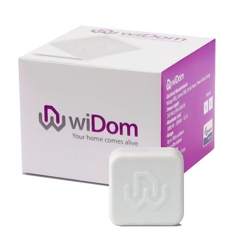
Product Picture


1 - Outputs status upon receipt of 1 click on its command
Defines the status of the output O1/O2 when the switch connected to I1/I2 receives 1 Click.Size: 1 byte
Default: 1
Minimum: 0
Maximum: 0
Possible values
| From | To | Desription |
|---|---|---|
| 1 | 1 | TOGGLE |
| 2 | 2 | ON |
| 3 | 3 | OFF |
| 4 | 4 | IGNORE |
2 - Outputs status upon receipt of 2 clicks on its command
Defines the status of the output O1/O2 when the switch connected to I1/I2 receives 2 Click.Size: 1 byte
Default: 1
Minimum: 0
Maximum: 0
Possible values
| From | To | Desription |
|---|---|---|
| 1 | 1 | TOGLE |
| 2 | 2 | ON |
| 3 | 3 | OFF |
| 4 | 4 | IGNORE |
3 - Type of outputs
Defines if the outputs are controlled individually, as a traditional device with two channels, or if its behaviour simulates a single pole double throw relay.Size: 1 byte
Default: 0
Minimum: 0
Maximum: 0
Possible values
| From | To | Desription |
|---|---|---|
| 0 | 0 | Channel 1 and Channel 2 are controlled individually |
| 1 | 127 | The two channels are in opposite status. If the Channel 1 is close the Channel 2 is open, if the Channel 1 is open the Channel 2 is close. The value of the parameter defines the closing delay of the relay in tenth of seconds |
4 - Number of clicks that activate the control of the associated devices
Defines the number of clicks on the Switch 1 or Switch 2 that enable the control of the correspondent associated devices.Size: 1 byte
Default: 0
Minimum: 0
Maximum: 0
Possible values
| From | To | Desription |
|---|---|---|
| 1 | 1 | Associated devices are controlled by 1 Click on the correspondent external switch |
| 2 | 2 | Associated devices are controlled by 2 Clicks on the correspondent external switch |
5 - Level used to control the devices associated to group 2 and 3
Defines how to control the devices associated to group 2 and 3.Size: 1 byte
Default: 100
Minimum: 0
Maximum: 0
Possible values
| From | To | Desription |
|---|---|---|
| 0 | 0 | The associated devices are switched OFF |
| -1 | -1 | The associated devices are switched ON |
| 1 | 99 | The associated devices (dimmer, roller shutters) are set to the indicated level (only for devices associated to group 3) |
| 100 | 100 | If the Relay 1 is ON/OFF, the associated devices are ON/OFF |
| 101 | 101 | If the Relay 1 is ON the associated devices are ON; if it is OFF no action is taken on the associated devices |
| 102 | 102 | If the Relay 1 is OFF the associated devices are OFF; if it is ON no action is taken on the associated devices |
| 103 | 103 | If the Relay 1 is ON the associated devices are OFF; if it is OFF no action is taken on the associated devices |
| 104 | 104 | If the Relay 1 is OFF the associated devices are ON; if it is ON no action is taken on the associated devices |
| 105 | 105 | If the Relay 1 is ON/OFF, the associated devices are OFF/ON |
| 106 | 106 | No action is taken on the associated devices |
6 - Level used to control the devices associated to group 4 and 5
Defines how to control the devices associated to group 4 and 5.Size: 1 byte
Default: 100
Minimum: 0
Maximum: 0
Possible values
| From | To | Desription |
|---|---|---|
| 0 | 0 | The associated devices are switched OFF |
| -1 | -1 | The associated devices are switched ON |
| 1 | 99 | The associated devices (dimmer, roller shutters) are set to the indicated level (only for devices associated to group 5) |
| 100 | 100 | If the Relay 2 is ON/OFF, the associated devices are ON/OFF |
| 101 | 101 | If the Relay 2 is ON the associated devices are ON; if it is OFF no action is taken on the associated devices |
| 102 | 102 | If the Relay 2 is OFF the associated devices are OFF; if it is ON no action is taken on the associated devices |
| 103 | 103 | If the Relay 2 is ON the associated devices are OFF; if it is OFF no action is taken on the associated devices |
| 104 | 104 | If the Relay 2 is OFF the associated devices are ON; if it is ON no action is taken on the associated devices |
| 105 | 105 | If the Relay 2 is ON/OFF, the associated devices are OFF/ON |
| 106 | 106 | No action is taken on the associated devices |
10 - Timer to switch ON the Channel 1
Defines the time after which the Channel 1 is switched ON.Size: 2 bytes
Default: 0
Minimum: 0
Maximum: 0
Possible values
| From | To | Desription |
|---|---|---|
| 0 | 0 | Timer disabled |
| 1 | 32000 | After this time the relay of the Channel 1 is ON |
11 - Timer to switch ON the Channel 2
Defines the time after which the Channel 2 is switched ON.Size: 2 bytes
Default: 0
Minimum: 0
Maximum: 0
Possible values
| From | To | Desription |
|---|---|---|
| 0 | 0 | Timer disabled |
| 1 | 32000 | After this time the relay of the Channel 2 is ON |
12 - Timer to switch OFF the Channel 1
Size: 2 bytes
Default: 0
Minimum: 0
Maximum: 0
Possible values
| From | To | Desription |
|---|---|---|
| 0 | 0 | Timer disabled |
| 1 | 32000 | Timer disabled |
13 - Timer to switch OFF the Channel 2
Defines the time after which the Channel 2 is switched OFF.Size: 2 bytes
Default: 0
Minimum: 0
Maximum: 0
Possible values
| From | To | Desription |
|---|---|---|
| 0 | 0 | Timer disabled |
| 1 | 32000 | After this time the relay of the Channel 2 is OFF |
20 - Outputs status upon receipt of a Multi-Channel Basic Set command
The two channels can be controlled individually by Z-Wave network. The status of the channels upon receipt of a Multi-Channel Basic Set command is defined by the value set on the parameter.Size: 1 byte
Default: 1
Minimum: 0
Maximum: 0
Possible values
| From | To | Desription |
|---|---|---|
| 1 | 1 | AS RECEIVED |
| 2 | 2 | IGNORE IF ON |
| 3 | 3 | IGNORE IF OFF |
| 4 | 4 | IGNORE |
21 - Outputs status upon receipt of a Basic Set command
The channels of the device can be controlled individually from all other Z-Wave devices that support the multichannel feature. In order to support also the integration with no-multichannel systems, this parameter allows to define if the receipt of a no-multichannel command controls only the Channel 1 or bothSize: 1 byte
Default: 3
Minimum: 0
Maximum: 0
Possible values
| From | To | Desription |
|---|---|---|
| 1 | 1 | CHANNEL 1 |
| 3 | 3 | BOTH CHANNELS |
60 - Start-up status
Defines the status of the device following a restart.Size: 1 byte
Default: 4
Minimum: 0
Maximum: 0
Possible values
| From | To | Desription |
|---|---|---|
| 0 | 0 | Both Relay 1 and Relay 2 OFF |
| 1 | 1 | Relay 1 ON, Relay 2 OFF |
| 2 | 2 | Relay 1 OFF, Relay 2 ON |
| 3 | 3 | Both Relay 1 and Relay 2 ON |
| 4 | 4 | Status prior to restart |
61 - Configuration reset
Size: 1 byte
Default: 4
Minimum: 0
Maximum: 0
Possible values
| From | To | Desription |
|---|---|---|
| 0 | 0 | The device is reset to the original factory settings |
| 1 | 1 | All associations and only the associations are reset |
| 2 | 2 | The associations are maintained while all other configuration parameters are reset to the original factory settings, except for the specific configuration. |
| 3 | 3 | The device will be restarted |
| 4 | 4 | IGNORE |
62 - Type of external switch
Size: 1 byte
Default: 4
Minimum: 0
Maximum: 0
Possible values
| From | To | Desription |
|---|---|---|
| 0 | 0 | The actions on the external switch are ignored. In this mode, the device can only be controlled via the network. |
| 1 | 1 | The external switch is a normally open button |
| 2 | 2 | The external switch is a traditional switch |
| 4 | 4 | After the first single click on the external switch, the system automatically determines the type of external switch used and sets the parameter with the new value accordingly. |
If the device is not included into a Z-Wave network, a single click on the (B) button or on one of the external switches will launch the process of traditional inclusion. If the device inclusion procedure does not start within 2 seconds, the Network Wide Inclusion network will be launched lasting a variable amount of time between 15-30 seconds.
Only a controller can remove a device from the network. WiDom Universal Double Switch is compatible with all Z-Wave certified controllers. After the exclusion procedure has been activated by the controller, the device can be removed, putting it in Exclusion Mode by three consecutive clicks on the (B) button or on the external switch, when available.
The device can be reset ot the factory reset by six consecutive clicks. This procedure shuld be used only if the primary controller is missing or inoperable.
The firmware update procedure must be enabled on the device with four consecutive clicks. The activation lasts 10 seconds, after which the firmware update procedure will need to be re-enabled if it has not been activated in the first instance.