Philio
Smart Energy Plug In Switch
PAN15-1
On/Off Power Switch
01
SD3502
6.51.06
0x013C (316)
0x0001 (1)
0x0028 (40)
ZC10-16010002
2015-12-11 13:53:50.6256
N/A
Enhanced 232 Slave
Always On Slave
This plug-in ON/OFF switch PAN15 is a security enabled wireless switch, based on Z-Wave Plus technology. The plug-in ON/Off switch is able to detect current wattege and overload wattage of connected light or appliances.
This plug-in ON/OFF switch PAN15 is a security enabled wireless switch, based on Z-Wave Plus technology. Z-Wave PlusTM enabled devices displaying the Z-Wave PlusTM logo can also be used with it regardless of the manufacturer, and can also be used in other manufacturer’s Z-WaveTM enabled networks. Remote On/Off control of the connected load is possible with other manufacturer’s wireless Controller. Each switch is designed to act as a repeater. Repeaters will re-transmit the RF signal to ensure that the signal is received by its intended destination by routing the signal around obstacles and radio dead spots. Because PAN15 supports Security Command Class, it can learn with Secured controller. Its functionality and supported command classes is identical when included as a secure and non-secure device. This plug-in ON/OFF switch is able to detect instance wattage (1560W/UL/TW/JP) and overload current (14.5A) of connected lights or appliances. When detecting overload state, the Switch will be disabled and its On/Off button will be lockout of which LED will flash quickly. However, unplug and re-connect the switch will reset its overload condition to normal status. Adding to Z-WaveTM Network In the front casing, there is an On/Off button with LED indicator which is used to toggle switch on and off or carry out inclusion, exclusion, reset or association. When first power is applied, its LED flashes on and off alternately and repeatedly at 0.5 second intervals. It implies that it has not been assigned a node ID and start auto inclusion. Auto Inclusion The function of auto inclusion will be executed as long as the switch does not have Node ID and just plug the switch into a wall outlet. Note: Auto inclusion timeout is 2 minute during which the node information of explorer frame will be emitted once several seconds. Unlike “inclusion” function as shown in the table below, the execution of auto inclusion is free from pressing the On/Off button on the Switch. The table below lists an operation summary of basic Z-Wave functions. Please refer to the instructions for your Z-WaveTM Certificated Primary Controller to access the Setup function, and to include/exclude/associate devices
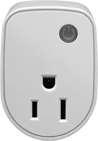
Product Picture


1 - Watt Meter Report Period
If the setting is configured for 1hour (set value =720), the PAN15 will report its instant power consumption every 1 hour to Group1 node. The maximum interval to report its instant power consumption is 45 hours (5s*32767/3600=45hr).Size: 2 bytes
Default: 720
Minimum: 0
Maximum: 0
Possible values
| From | To | Desription |
|---|---|---|
| 1 | 32767 | 720*5s=3600s=1 hour |
2 - KWH Meter Report Period
If the setting is configured for 1hour (set value =6), the PAN15 will report its Accumulated Power Consumption (KW/h) every 1 hour to Group1 node. The maximum interval to report its Accumulated Power Consumption (KW/h) is 227.55 days (10min*32767/1440=227.55 days).Size: 2 bytes
Default: 6
Minimum: 0
Maximum: 0
Possible values
| From | To | Desription |
|---|---|---|
| 1 | 32767 | 6*10min=1 hour |
3 - Threshold of current for Load Caution
This is a warning when the current of load over the preset threshold value, if the setting value is 1300, when the load current of Relay1 over this value, PAN15 will send current meter report to warn the Group1 node, the Range of the setting value is from 10 to 1300,and the default value is 1300.Size: 2 bytes
Default: 1300
Minimum: 0
Maximum: 0
Possible values
| From | To | Desription |
|---|---|---|
| 10 | 1300 | 1300*0.01A = 13A |
4 - Threshold of KWh for Load Caution
This is a warning when the KWh of load over the preset threshold value, If the setting value is 10000, when the Accumulated Power Consumption of Relay1 over this value, PAN15 will send KWH meter report to warn the Group1 node, minimum value is 1KWh and default value is 10000 kWh.Size: 2 bytes
Default: 10000
Minimum: 0
Maximum: 0
Possible values
| From | To | Desription |
|---|---|---|
| 1 | 10000 | 10000*1KWH=10000KWH |
5 - Restore switch state mode
Whenever the AC power return from lost, PAN15 will restore the switch state which could be SWITCH OFF、LAST SWITCH STATE、SWITCH ON. The default setting is LAST SWITCH STATE.Size: 1 byte
Default: 1
Minimum: 0
Maximum: 0
Possible values
| From | To | Desription |
|---|---|---|
| 0 | 0 | 0 : Switch off |
| 1 | 1 | 1 : Last switch state |
| 2 | 2 | 2 : Switch on |
6 - Mode of switch off function
When the mode of switch On/Off is set to 0, any command of switch off will be disabled and the On/Off function of include button will be disabled. The default setting is enable mode.Size: 1 byte
Default: 1
Minimum: 0
Maximum: 0
Possible values
| From | To | Desription |
|---|---|---|
| 0 | 0 | 0 : Disable |
| 1 | 1 | 1 : Enable |
7 - LED indication mode
1. Show Switch State:When switch is on, LED is on. When switch is off, LED is off. The default setting is Show Switch State. 2. Show Night mode:When switch is on, LED is off. When switch is off, LED is on.Size: 1 byte
Default: 1
Minimum: 0
Maximum: 0
Possible values
| From | To | Desription |
|---|---|---|
| 1 | 1 | 1 : Show switch state |
| 2 | 2 | 2 : Show night mode |
8 - Auto off timer
Whenever PAN15 switches to on, the auto off timer begin to count down. After the timer decrease to zero, it will switch to off automatically. However if Auto off timer is set as 0, the auto off function will be disabled. The default setting is 0.Size: 2 bytes
Default: 0
Minimum: 0
Maximum: 0
Possible values
| From | To | Desription |
|---|---|---|
| 0 | 0 | 0 : Disable auto off function |
| 1 | 32767 | 1-0x7FFF : 1s ~ 32767s |
9 - RF off command mode
Whenever a switch off command, BASIC_SET、BINARY_SWITCH_SET、SWITCH_ALL_OFF, is received, it could be interpreted as 4 variety of commands. 1. Switch Off:It switches to OFF state. The default setting is Switch Off. 2. Ignore:The switch off command will be ignored. 3. Switch Toggle:It switches to the inverse of current state. 4. Switch On:It switches to ON state.Size: 1 byte
Default: 0
Minimum: 0
Maximum: 0
Possible values
| From | To | Desription |
|---|---|---|
| 0 | 0 | 0 : Switch off |
| 1 | 1 | 1 : Ignore |
| 2 | 2 | 2 : Switch toggle |
| 3 | 3 | 3 : Switch on |
11 - Switch status report mode
Whenever the status of switches changes, it will send a Binary Switch report to the group1 node. The default setting is 1 (Enable).Size: 1 byte
Default: 1
Minimum: 0
Maximum: 0
Possible values
| From | To | Desription |
|---|---|---|
| 0 | 0 | 0 : Disable |
| 1 | 1 | 1 : Enable |
1.Put your Z-Wave controller into inclusion mode by following the instructions provided by the controller manufacturer. 2. Pressing On/Off button three times within 2 seconds will enter inclusion mode.
1.Put your Z-Wave controller into exclusion mode by following the instructions provided by the controller manufacturer. 2. Pressing On/Off button three times within 2 seconds will enter exclusion mode. 3.Node ID has been excluded.
Use this procedure only in the event that the primary controller is lost or otherwise inoperable. 1. Pressing On/Off button three times within 2 seconds will enter inclusion mode. Use this procedure only in the event that the primary controller is lost or otherwise inoperable. 2. Within 1 second, press On/Off button again for 5 seconds. 3. IDs are reset.