FIBARO
FIBARO Door/Window Sensor
FGK-10X
Notification Sensor
HW: 1 FW: 3.02
ZM5202
6.51.06
0x010F (271)
0x0701 (1793)
0x2001 (8193)
ZC10-16025002
2016-02-02 09:46:31.7948
N/A
Enhanced 232 Slave
Reporting Sleeping Slave
FIBARO Door/Window is a wireless, battery powered, Z-Wave compatible reed sensor.
FIBARO Door/Window Sensor is a wireless, battery powered reed sensor compatible with the Z-Wave Plus standard. Changing the device’s status will automatically send signal to the Z-Wave controller and associated devices. Sensor can be used to trigger scenes and everywhere there is a need for information about opening or closing of doors, windows, garage doors, etc. Opening is detected by separating the sensor’s body and the magnet. In addition the FIBARO Door/Window Sensor supports one DS18B20 temperature sensor and has one potential free input. The FIBARO Door / Window Sensor is available in seven colors: white, silver, black, pearl powder, cappuccino, truffle surprise and dark chocolate. https://www.youtube.com/watch?v=K35uFXoa5c0
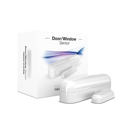
Product Picture


1 - Operation mode
Parameter defines device operation mode. CAUTION Do not install the magnet if the device is not used as a Door/Window Sensor, as it might lead to the malfunction of the device.Size: 1 byte
Default: 0
Minimum: 0
Maximum: 0
Possible values
| From | To | Desription |
|---|---|---|
| 0 | 0 | Door/Window Sensor or external alarm sensor |
| 1 | 1 | external button |
2 - Door/Window or alarm status
Parameter defines state of the sensor when the magnet is close. If the alarm sensor is connected, it determines the output type. Parameter inactive in external button mode (parameter 1 set to 1).Size: 1 byte
Default: 0
Minimum: 0
Maximum: 0
Possible values
| From | To | Desription |
|---|---|---|
| 0 | 0 | door/window closed |
| 1 | 1 | door/window opened |
3 - Visual LED indications
This parameter defines events indicated by the visual LED indicator. Disabling events might extend battery life. NOTE Values of parameter 3 may be combined, e.g. 1+2=3 means opening/closing and wake up will be indicated by the visual indicator.Size: 1 byte
Default: 6
Minimum: 0
Maximum: 0
Possible values
| From | To | Desription |
|---|---|---|
| 0 | 0 | no indications |
| 1 | 1 | indication of opening/closing status change (input IN) |
| 2 | 2 | indication of wake up (1 x click or periodical) |
| 4 | 4 | indication of device tampering |
4 - Range test after double click
Allows to enable activation of Z-Wave range test with double click of a TMP button.Size: 1 byte
Default: 0
Minimum: 0
Maximum: 0
Possible values
| From | To | Desription |
|---|---|---|
| 0 | 0 | disabled |
| 1 | 1 | enabled |
10 - 2nd association group triggers
Parameter defines events which result in sending on/off commands to devices added to the 2nd association group. These commands are sent alternately to switch the devices on and off. Commands represent the values of BASIC SET command frames. Parameter is inactive in external button mode (parameter 1 set to 1).Size: 1 byte
Default: 0
Minimum: 0
Maximum: 0
Possible values
| From | To | Desription |
|---|---|---|
| 0 | 0 | switch after opening and closing |
| 1 | 1 | switch after opening |
| 2 | 2 | switch after closing |
11 - Commands sent to 2nd association group
Command frames sent to devices added to the 2nd association group.Size: 1 byte
Default: 2
Minimum: 0
Maximum: 0
Possible values
| From | To | Desription |
|---|---|---|
| 0 | 0 | ON |
| 1 | 1 | OFF |
| 2 | 2 | ON & OFF |
12 - Value of ON command frame sent to 2nd association group
The value of 0 turns OFF the device, 255 turns it ON. In case of associating the Dimmer or Roller Shutter module, values 1-99 allow to set an associated device to a specified level.Size: 2 bytes
Default: 255
Minimum: 0
Maximum: 0
Possible values
| From | To | Desription |
|---|---|---|
| 0 | 99 | turns OFF the device |
| 255 | 255 | turns it ON |
13 - Value of OFF command frame sent to 2nd association group
The value of 0 turns OFF the device, 255 turns it ON. In case of associating the Dimmer or Roller Shutter module, values 1-99 allow to set an associated device to a specified level.Size: 2 bytes
Default: 0
Minimum: 0
Maximum: 0
Possible values
| From | To | Desription |
|---|---|---|
| 0 | 99 | turns OFF the device |
| 255 | 255 | turns it ON |
14 - Time delay of ON command frame
Time period after which ON command frame will be sent.Size: 2 bytes
Default: 0
Minimum: 0
Maximum: 0
Possible values
| From | To | Desription |
|---|---|---|
| 0 | 32400 | time in seconds |
15 - Time delay of OFF command frame
Time period after which OFF command frame will be sent.Size: 2 bytes
Default: 0
Minimum: 0
Maximum: 0
Possible values
| From | To | Desription |
|---|---|---|
| 0 | 32400 | time in seconds |
20 - Type of sent alarm frames
Type of control frames transmitted to the main controller and 3rd association group “Alarm”. If an external sensor is connected to IN input, it is possible to choose its functionality. Otherwise it is recommended to set this parameter to default value. CAUTION In order to activate new settings of parameter 20, it is required to remove and re-add the device to the main Z-Wave controller. This parameter is not reset during removal process.Size: 1 byte
Default: 0
Minimum: 0
Maximum: 0
Possible values
| From | To | Desription |
|---|---|---|
| 0 | 0 | Door/Window Sensor (General Purpose Alarm) |
| 1 | 1 | smoke sensor (Smoke Alarm) |
| 2 | 2 | CO detector (CO Alarm) |
| 3 | 3 | CO2 detector (CO2 Alarm) |
| 4 | 4 | high temperature sensor (Heat Alarm) |
| 5 | 5 | flood sensor (Water Alarm) |
30 - Delay of tamper alarm cancellation
Time period after which a tamper alarm will be cancelled.Size: 2 bytes
Default: 5
Minimum: 0
Maximum: 0
Possible values
| From | To | Desription |
|---|---|---|
| 0 | 32400 | time in seconds |
31 - Reporting tamper alarm cancellation
Reporting cancellation of tamper alarm to the controller and 5th association group.Size: 1 byte
Default: 1
Minimum: 0
Maximum: 0
Possible values
| From | To | Desription |
|---|---|---|
| 0 | 0 | do not send tamper cancellation report |
| 1 | 1 | send tamper cancellation report |
50 - Interval of temperature measurements
This parameter defines how often the temperature will be measured. The shorter the time, the more frequently the temperature will be measured, but the battery life will shorten.Size: 2 bytes
Default: 300
Minimum: 0
Maximum: 0
Possible values
| From | To | Desription |
|---|---|---|
| 0 | 0 | temperature measurements disabled |
| 5 | 32400 | time in seconds |
51 - Temperature reports threshold
This parameter defines the change of temperature in comparison with last reported, resulting in temperature report being sent to the main controller.Size: 2 bytes
Default: 10
Minimum: 0
Maximum: 0
Possible values
| From | To | Desription |
|---|---|---|
| 0 | 0 | temperature reports based on threshold disabled |
| 1 | 300 | temperature threshold |
52 - Interval of temperature reports
Interval of temperature reports. NOTE Temperature measurement is performed before sending any report (regardless of parameter no. 50). Excessive reporting can affect battery lifetime. Reporting on the basis of temperature change (parameter no. 51) is recommended.Size: 2 bytes
Default: 0
Minimum: 0
Maximum: 0
Possible values
| From | To | Desription |
|---|---|---|
| 0 | 0 | periodic temperature reports disabled |
| 5 | 32400 | time in seconds |
53 - Temperature offset
The value to be added to the actual temperature, measured by the sensor (temperature compensation).Size: 4 bytes
Default: 0
Minimum: 0
Maximum: 0
Possible values
| From | To | Desription |
|---|---|---|
| -1000 | 1000 | -100 – 100 degrees Celsius, in 0,1 degrees steps |
54 - Temperature alarm reports
Temperature alarms reported to the Z-Wave controller. Thresholds are set in parameters 55 and 56.Size: 1 byte
Default: 0
Minimum: 0
Maximum: 0
Possible values
| From | To | Desription |
|---|---|---|
| 0 | 0 | temperature alarms disabled |
| 1 | 1 | high temperature alarm |
| 2 | 2 | low temperature alarm |
| 3 | 3 | high and low temperature alarms enabled |
55 - High temperature alarm threshold
If temperature is higher than set value, overheat notification will be sent and high temperature scene will be triggered (if activated).Size: 2 bytes
Default: 540
Minimum: 0
Maximum: 0
Possible values
| From | To | Desription |
|---|---|---|
| 0 | 1000 | 0 - 100 degrees Celsius, in 0,1 degrees steps |
56 - Low temperature alarm threshold
If temperature is lower than the set value, underheat notification will be sent and low temperature scene will be triggered (if activated).Size: 2 bytes
Default: 40
Minimum: 0
Maximum: 0
Possible values
| From | To | Desription |
|---|---|---|
| -300 | 700 | -30 - 70 degrees Celsius, in 0,1 degrees steps |
70 - Scene activation functionality
The device can trigger scenes using scene IDs assigned to different events. To deactivate all scenes set the value to 0. To activate all scenes set the value to 3903. CAUTION Every activated scene may shorten the battery life. NOTE Values of parameter 70 may be combined, e.g. 1+2=3 means scenes for opening and closing are sent. NOTE Scenes with IDs 12 to 15 are active only if parameter 1 is set to 1. In this case scenes with IDs 1 and 2 are sent after a single click.Size: 2 bytes
Default: 0
Minimum: 0
Maximum: 0
Possible values
| From | To | Desription |
|---|---|---|
| 1 | 1 | [ID 10] opening door/window (single click) |
| 2 | 2 | [ID 11] closing door/window (single click) |
| 4 | 4 | [ID 12] holding |
| 8 | 8 | [ID 13] releasing |
| 16 | 16 | [ID 14] double click |
| 32 | 32 | [ID 15] triple click |
| 256 | 256 | [ID 50] high temperature - door/window opened |
| 512 | 512 | [ID 50] high temperature - door/window closed |
| 1024 | 1024 | [ID 51] low temperature - door/window opened |
| 2048 | 2048 | [ID 51] low temperature - door/window closed |
71 - Alarm broadcast
Settings for broadcasting ON/OFF commands, sensor alarm and tamper alarm. Value other than 0 means alarms are sent in Broadcast Mode, to all devices only within the range of the device. They are not repeated by the mesh network. NOTE Values of parameter 71 may be combined, e.g. 1+2=3 means ON/OFF commands and sensor alarm are sent in Broadcast Mode.Size: 1 byte
Default: 0
Minimum: 0
Maximum: 0
Possible values
| From | To | Desription |
|---|---|---|
| 0 | 0 | broadcasts inactive |
| 1 | 1 | ON/OFF commands broadcast active |
| 2 | 2 | sensor alarm broadcast active |
| 4 | 4 | tamper alarm broadcast active |
72 - Associations in Z-Wave network Security Mode
This parameter defines how commands are sent in specified association groups: as secure or non-secure. Parameter is active only in Z-Wave network security mode. It does not apply to 1st group “Lifeline”. NOTE Operating in Z-Wave network security mode automatically disables sending alarms in broadcast mode. NOTE Values of parameter 72 may be combined, e.g. 1+2=3 means 2nd and 3rd group are sent as secure.Size: 1 byte
Default: 15
Minimum: 0
Maximum: 0
Possible values
| From | To | Desription |
|---|---|---|
| 0 | 0 | none of the groups sent as secure |
| 1 | 1 | 2nd group, Control, sent as secure |
| 2 | 2 | 3rd group, Alarm, sent as secure |
| 4 | 4 | 4th group, Sensor ZW3, sent as secure |
| 8 | 8 | 5th group, Tamper ZW3, sent as secure |
1) Open the cover. 2) Remove the battery blocker. 3) Close the cover. 4) Locate the sensor nearby the main Z-Wave controller. 5) Set the main Z-Wave controller into adding mode (see main controller’s operating manual). 6) Quickly, triple click the TMP button located on the bottom of the casing. 7) Wait for the device to be added to the system. 8) Successful adding will be confirmed by the controller. 9) Install the device using the attached self-adhesive pads.
1) Place the device within direct reange of the Z-Wave controller. 2) Make sure that Sensor's cover is closed. 3) Set the main Z-Wave controller into learning mode (see main controller’s operating manual). 4) Quickly, triple click the TMP button. 5) Wait for the device to be excluded from the system. Successful exclusion will be confirmed by the controller.
FIBARO Door/Window Sensor will wake up at a defined time interval and will ALWAYS try to communicate with the main controller. Setting wake up interval to 0 disables sending Wake Up Notification frame automatically. There is a possibility to wake up the device manually by a single TMP button click.
Resetting the device is not the recommended way of removing the device from the Z-Wave network. Use reset procedure only if the primary controller is missing or inoperable. 1) Take off the Sensor's cover and remove battery. 2) Install the battery while holding both TMP buttons (after mounting the device, one button is constantly pressed by the cover). 3) Release the TMP button within 5 seconds. 4) LED will blink 3 times to confirm launching of reset procedure. 5) Reset procedure may last up to 30 seconds. Do not remove the battery until reset is complete. 6) Reset will be confirmed by the six blinks of the LED.