Dragon Tech Industrial, Ltd.
In-Wall Dimmer ON/OFF Switch
WD-100
Light Dimmer Switch
FF
ZM5202
6.51.06
0x0184 (388)
0x4447 (17479)
0x3034 (12340)
ZC10-16020014
2016-02-29 09:41:01.1436
N/A
Enhanced 232 Slave
Always On Slave
WD-100 In Wall Dimmer Switch - Replaces existing wall switch - Remotely or manually turns On, Off, or dim lights - Fits standard wall plates - Z-Wave Plus certified with 500 series chipset - Functions as a Z-Wave signal repeater - Support Central Scene
- Works with incandescent and dimmable florescent (CFL) or LED lighting - ON/OFF status and location LED indicator - Fits into standard single or multiple gang junction box - Keypad can be replaced manually to match color with other wall switches - Over-The-Air firmware upgrade available with compatible gateway, Z-Wave static controller, or PC and software - Internal resettable fuse to protect from surge current - Manual reset capability - Support Central Scene
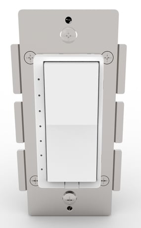
Product Picture


4 - the orientation of the ON/OFF on the rocker switch
the orientation of the ON/OFF on the rocker switch can be invertedSize: 1 byte
Default: 0
Minimum: 0
Maximum: 0
Possible values
| From | To | Desription |
|---|---|---|
| 0 | 0 | the connected light will turn ON by pressing the top side of the rocker switch and turn OFF by pressing the bottom side. |
| 1 | 1 | the connected light will turn OFF by pressing the top side of the rocker switch and turn ON by pressing the bottom side. |
9 - indicates the number of levels
The time interval of brightness change between dimming up and down can be adjusted Length: 1 Byte Valid Values: 1-99 (default = 1), indicates the number of levels the lighting will change when the timer runs out.Size: 1 byte
Default: 1
Minimum: 0
Maximum: 0
Possible values
| From | To | Desription |
|---|---|---|
| 1 | 99 | indicates the number of levels the lighting will change when the timer runs out. |
10 - indicates the time duration of each level
The time interval of brightness change between dimming up and down can be adjusted Valid Values: 1-255 (default = 3), indicates the time duration of each level.Size: 2 bytes
Default: 3
Minimum: 0
Maximum: 0
Possible values
| From | To | Desription |
|---|---|---|
| 1 | 22 | indicates the time duration of each level. |
| 0 | 0 |
1. Turn the connected lights ON/OFF by tapping the switch. Tapping and releasing the upper part of the rocker turns the appliance ON. Tapping and releasing the lower part of the rocker turns the appliance OFF. 2. Add(Include) the module to/from your Z-Wave network with your primary controller. Please refer to the instructions manual of your gateway or remote controller for details and procedures on how these actions can be done. 3. Normally, the sequence is as follows: when the inclusion process is prompted by your primary controller, single click and release the rocker switch to ON or OFF position. The controller should show that the action was successful. If the controller shows it was a fail, repeat the procedure.
1. Turn the connected appliance ON/OFF by tapping the switch. Tapping and releasing the upper part of the rocker turns the appliance ON. Tapping and releasing the lower part of the rocker turns the appliance OFF. 2. Delete(Exclude) the module to/from your Z-Wave network with your primary controller. Please refer to the instructions manual of your gateway or remote controller for details and procedures on how these actions can be done. 3. Normally, the sequence is as follows: when the exclusion process is prompted by your primary controller, single click and release the rocker switch. The controller should show that the action was successful. If the controller shows it was a fail, repeat the procedure.
Please use this procedure only in the event that the network primary controller is lost or otherwise inoperable. All Configuration Parameters can all be restored to their factory default settings by using your primary controller to delete/reset the device. To manually reset, tap the ON button twice quickly and then tap the OFF button twice quickly. Repeat the procedure to restore the settings to the factory default.
Z-Wave Plus introduces a new process for scene activation – “Central Scene Control”. Press and release the button, it will send a certain command to the central controller via the lifeline association group 1. This allows the controller to react to key pressed, key released and key held down. - Press and release the top button, “Scene 001 Key Pressed” preset by the Gateway will be turned ON. - Press the top button twice, “Scene 001 Key Pressed Twice” preset by the Gateway will be turned ON. - Press the top button 3 times, “Scene 001 Key Pressed 3 Times” preset by the Gateway will be turned ON. - Press and release the bottom button, “Scene 002 Key Pressed” preset by the Gateway will be turned ON. - Press the bottom button twice, “Scene 002 Key Pressed Twice” preset by the Gateway will be turned ON. - Press the bottom button 3 times, “Scene 002 Key Pressed 3 Times” preset by the Gateway will be turned ON.