Vivint
Vivint Element
CT200
Thermostat - HVAC
HW: 0 FW: 11.18:00.12:00.05
ZM5202
6.51.06
0x0098 (152)
0xC801 (51201)
0x000C (12)
ZC10-16045048
2016-03-10 13:37:57.9056
N/A
Enhanced Slave
Listening Sleeping Slave
Vivint Element is an elegantly simple smart thermostat that combines with Vivint’s system intelligence to deliver an unmatched balance of comfort & energy savings.
The Vivint Element Smart Thermostat has an elegantly simple design making it easy for anyone to use. It’s hidden display comes to life when you need it, providing clear information and simple controls. This simplicity purposefully masks Element’s true intelligence. Element works in concert with the Vivint SkyControl system, leveraging an unmatched understanding of home routines and activity levels. Element automatically and dynamically adjusts to match home activities and ensure a personalized balance of comfort & energy savings. Because Element uses the latest in Z-Wave technology, it is compatible with all common heating & cooling systems without the need for any new wiring. It can also be wirelessly updated, ensuring it will continue to evolve to meet consumers’ ever-changing comfort & energy savings needs.
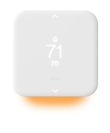
Product Picture


1 - Temperature Reporting Threshold
The Temperature Reporting Threshold Configuration Set Command sets the reporting threshold for changes in the ambient temperature as detected by the thermostat.Size: 1 byte
Default: 2
Minimum: 0
Maximum: 0
Possible values
| From | To | Desription |
|---|---|---|
| 0 | 4 | 0 disabled 1 0.5F |
2 - HVAC Settings
This parameter is used to set and retrieve the current HVAC settings of the thermostat..Size: 4 bytes
Default: 0
Minimum: 0
Maximum: 0
Possible values
| From | To | Desription |
|---|---|---|
| 0 | 0 | "Cooling Type (0, 1, 2, 3) Heating Type (0, 1, 2, 3) Heating Fuel (1, 2, 3, 4, 5) Number of Heat Stages (not Heat Pump) / Number of Aux Stages (Heat Pump) (1, 2)  A Terminal Assignment (0, 1, 2, 3, 4) Number of Heat Pump Stages (1, 2)  O/B Wire Selection (1,2)  Cooling Stages (1, 2)" |
3 - Utility Lock Enable/Disable
The Utility Lock Configuration Set command enables or disables the utility lock. If the utility lock is enabled, the setpoint cannot be modified directly via the thermostat screen.Size: 1 byte
Default: 0
Minimum: 0
Maximum: 0
Possible values
| From | To | Desription |
|---|---|---|
| 0 | 255 | If set to 0, the utility lock is disabled, all other values will enable the utility lock. |
4 - C-Wire / Battery Status
The C-Wire / Battery Status Configuration Report Command returns the status of the thermostat power source. The power state is fixed when the thermostat joins the network.Size: 1 byte
Default: 0
Minimum: 0
Maximum: 0
Possible values
| From | To | Desription |
|---|---|---|
| 1 | 2 | C-Wire (0x01) or Battery (0x02) |
5 - Humidity Reporting Threshold
The Humidity Threshold Configuration Set Command sets the reporting threshold for changes in the relative humidity as detected by the thermostat.Size: 1 byte
Default: 2
Minimum: 0
Maximum: 0
Possible values
| From | To | Desription |
|---|---|---|
| 0 | 3 | 0=disabled 1=3%RH 2=5%RH 3=10%RH |
6 - Auxiliary/Emergency
The Auxiliary/Emergency configuration command enables or disables auxiliary / emergency heating in the thermostat.Size: 1 byte
Default: 0
Minimum: 0
Maximum: 0
Possible values
| From | To | Desription |
|---|---|---|
| 0 | 1 | 0=disabled 1=enabled |
7 - Thermostat Swing Temperature
The Thermostat Swing Temperature configuration command sets swing temperature on the thermostat.Size: 1 byte
Default: 2
Minimum: 0
Maximum: 0
Possible values
| From | To | Desription |
|---|---|---|
| 1 | 8 | The thermostat swing temperature is in units of 0.5 degrees Fahrenheit. A value of 0x01 is 0.5F and 0x02 is 1.0F. The supported values may vary from thermostat to thermostat but typically the allowed values are 0.5F (0x01) to 4.0F (0x08). |
8 - Thermostat Diff Temperature
The Thermostat Differential Temperature configuration command sets the differential temperature for multi-stage HVAC systems.Size: 2 bytes
Default: 1028
Minimum: 0
Maximum: 0
Possible values
| From | To | Desription |
|---|---|---|
| 0 | 0 | "The Thermostat Differential Mode determines which differential temperature to set. Valid values are 0x00 (Heat) or Cool (0x01) The thermostat differential temperature is in units of 0.5 degrees Fahrenheit. A value of 0x04 is 2.0F and 0x06 is 3.0F. The differential temperature must be an integer value. Non-integer values, such as 1.5F (0x03), should not be used. The supported values may vary from thermostat to thermostat but typically, the allowed values are 2.0F (0x04) to 6.0F (0x0C). " |
9 - Thermostat Recovery Mode
The Thermostat Recovery Mode configuration command sets the HVAC recovery mode type. The recovery mode determines when additional HVAC stages are turned off as the ambient temperature returns to the target temperature.Size: 1 byte
Default: 2
Minimum: 0
Maximum: 0
Possible values
| From | To | Desription |
|---|---|---|
| 1 | 2 | The Thermostat Recovery Mode can be either fast (0x01) or economy (0x02). |
10 - Temperature Reporting Filter
The Temperature Reporting Filter configuration command sets upper and lower bounds of the ambient temperature reporting. The thermostat will not report ambient temperature changes if the ambient temperature is below the upper bound or above the lower bound.Size: 4 bytes
Default: 32000
Minimum: 0
Maximum: 0
Possible values
| From | To | Desription |
|---|---|---|
| 0 | 0 | "Byte 1 is the lower bound and can be 0 to 124 Byte 2 is the upper bound and can be 0 to 124 " |
11 - Simple UI Mode Enable/Disable
The parameter is set the auxiliary Simple Mode.Size: 1 byte
Default: 0
Minimum: 0
Maximum: 0
Possible values
| From | To | Desription |
|---|---|---|
| 0 | 1 | 0=Normal 1=Simple |
12 - Multicast Enable/Disable
This parameter controls how the thermostat sends unsolicited reports.Size: 1 byte
Default: 0
Minimum: 0
Maximum: 0
Possible values
| From | To | Desription |
|---|---|---|
| 0 | 1 | If set to 0, multicast is disabled, if set to 1, multicast is enabled. |
13 - Main Display Selection (CT110)
This configuration Param on the CT110 sets what information is displayed in the main thermostat display area (the largest central numbers on the display).Size: 1 byte
Default: 1
Minimum: 0
Maximum: 0
Possible values
| From | To | Desription |
|---|---|---|
| 1 | 2 | 1=Temperatue 2=RH |
14 - Save Energy Mode Type (CT110)
This configuration value is used to read/write what behavior Save Energy Mode causes in the thermostat when the thermostat enters Save Energy Mode.Size: 1 byte
Default: 2
Minimum: 0
Maximum: 0
Possible values
| From | To | Desription |
|---|---|---|
| 1 | 255 | "1 = Adjust target by delta (see 0x50, 58) 2 = Least consuming point in the running program 3 = Save energy absolute setpoint (Radio must adjust setpoint) 255 = Save Energy not supported by thermostat (read-only value) " |
15 - Fan Timer (CT200)
This configuration is used to activate the fan with an automatic shut-off timer.Size: 1 byte
Default: 0
Minimum: 0
Maximum: 0
Possible values
| From | To | Desription |
|---|---|---|
| 0 | 60 | 0, 15 min, 30 min, 60 min |
16 - Humidity Control Activation (CT200)
This parameter is a pass-through. All the logic is handled by the thermostat based on the A terminal assignment.Size: 2 bytes
Default: 1
Minimum: 0
Maximum: 0
Possible values
| From | To | Desription |
|---|---|---|
| 0 | 0 | "Byte 1 can be 0 or 1 Byte 2 can be 1 or 3" |
17 - Temperature Calibration (CT200)
This configuration is used to set the temperature offset of the thermostat.Size: 1 byte
Default: 0
Minimum: 0
Maximum: 0
Possible values
| From | To | Desription |
|---|---|---|
| -6 | 6 | The valid values are from -6 to 6. |
18 - Display Units (CT200)
This configuration is used to set units used by the device to display temperature.Size: 1 byte
Default: 0
Minimum: 0
Maximum: 0
Possible values
| From | To | Desription |
|---|---|---|
| 0 | 1 | 0=Fahrenheit 1=Celsius |
Press and hold side button to enter menu screen. Navigate to Installer > Network to selection option to include to a Z-Wave network.
Press and hold side button to enter menu screen. Navigate to Installer > Network to select option to exclude from a Z-Wave network.
Press any button to wake up thermostat. If “Wake up on Approach” is enabled, simply approach the thermostat to wake up.
Press and hold side button to enter menu screen. Navigate to Installer > Reset and select Yes to reset to factory default settings. Use this procedure only in the event that the network primary controller is missing or otherwise inoperable.