FortrezZ LLC
Flow Meter
FMI
Multilevel Sensor
HW: 5 FW: 1.16
ZM5202
6.51.06
0x0084 (132)
0x0473 (1139)
0x0110 (272)
ZC10-16045038
2016-03-31 11:48:02.7704
N/A
Enhanced 232 Slave
Always On Slave
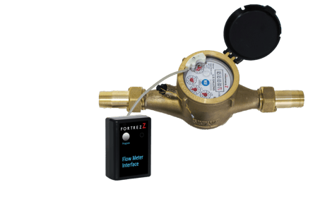
Take Control of your water! Flow meter does just that by tracking water consumption and flow. Get reports with your daily, weekly, and monthly consumption data. Flow meter sends notifications if water is flowing or not, and detects leaks or unwanted use.
Information is power! With flow meter, you have the power to automate and manage water consumption and leak detection in your home or building. This is an integral part to a complete water management solution! Flow meter tracks water usage and reports in gallons. Track your households water usage! Drill into reports and find out where your peak consumption is and make changes to reduce your water bills. Flow meter also tells you if water is flowing or not. It knows if the flow is small (like a toilet running) or large (a garden hose left on). This can be used to detect leaks, faulty appliances, or fixtures left on. To add to it's capabilities, flow meter checks the temperature of the nearby surroundings to make sure the pipes don't freeze by sending you temperature reports. There's also a backup battery just in case power is interrupted. You wont have to worry about lost data or a lack of leak monitoring. Plumbed on the water main, flow meter is sure to be a valuable part of your home automation & leak prevention system.


1 - Temperature Low Threshold
Set threshold for Low Temperature trigger. Default set to 4⁰C (39⁰F)Size: 1 byte
Default: 4
Minimum: 0
Maximum: 0
Possible values
| From | To | Desription |
|---|---|---|
| 246 | 69 | -10 to 69⁰C |
| 0 | 0 |
2 - Temperature High Threshold
Set threshold for High Temperature trigger. Default set to 70⁰C (158⁰F)Size: 1 byte
Default: 70
Minimum: 0
Maximum: 0
Possible values
| From | To | Desription |
|---|---|---|
| 247 | 70 | -9 to 70⁰C |
| 0 | 0 |
3 - Meter Count
Meter Count reset back to 0 or set value.Size: 1 byte
Default: 0
Minimum: 0
Maximum: 0
Possible values
| From | To | Desription |
|---|---|---|
| 0 | 2147483647 | 0 TO 2147483647 count rolls over at 99,999,999 |
| 0 | 0 |
4 - Meter Reporting Interval
Meter Report Interval, while liquid flow is detected (in increments of 10 seconds). If 0 is set, then no continuous reporting during liquid flow; in this case, a report is sent every 10 hours whether or not flow is detected. Default value of 6 represents 60 seconds (1 minute).Size: 1 byte
Default: 6
Minimum: 0
Maximum: 0
Possible values
| From | To | Desription |
|---|---|---|
| 0 | 255 | 0 to 2,550 seconds (0XFF) |
| 0 | 0 |
5 - Meter Threshold (low vs High flow)
Use this to set the Gallons count per interval. Default is 50 (5 gallons). . If this number of meter counts is exceeded during the above Meter Report Interval, then General Multilevel Sensor Report (MLS) with value=255 and large threshold leak notification messages are sent. If less than the threshold, then MLS value=128 and low threshold leak notification messages are sent. If flow stops, then MLS value = 0 and inactive water notification messages are sent.Size: 1 byte
Default: 50
Minimum: 0
Maximum: 0
Possible values
| From | To | Desription |
|---|---|---|
| 0 | 65535 | 0 to 65535 (0XFFFF) |
| 0 | 0 |
6 - MultiLevel Sensor Report vs Notification Toggle
Use this to toggle between Notification Command Class & MultiLevel Sensor report. By default, FMI uses Notification Command Class (Water Flow). Set a Non-zero value to disable Notification Command class and enable the Multi Level Sensor report instead. Multi level sensor report will send (0, 128, or 255). Notification command class will send (Water Flow V7 w/ parm 1,2, 3)Size: 1 byte
Default: 1
Minimum: 0
Maximum: 0
Possible values
| From | To | Desription |
|---|---|---|
| 0 | 255 | 0 = Notification, 1= MLS report |
| 0 | 0 |
1) Set up the inclusion mode at the controller; 2) Briefly press the switch once and the controller will indicate the unit has been included in the network. Also, the LED will blink when the inclusion completes.
1) Set up the exclusion mode at the controller; 2) Briefly press the switch once and then release. The controller will indicate the unit has been removed from the network. The LED will blink when the exclusion completes.
The FMI will send the Node information frame when the switch is briefly pressed. This is primarily used for inclusion; however, status information is also sent after a button press.
Device Reset to Factory Defaults – Press and hold the button for 15 or more seconds and then release. This can be done while the device is either in or out of a network, but not while in NWI mode. CAUTION – When a reset is done in-network, the device will no longer be in the network. All configurations and associations will be set to default.
Enter Over-the-Air (OTA) Firmware Update mode – Quickly press the program button three times while in-network. Warning – This should not be done unless a firmware update will be immediately started at the controller. Do not allow the OTA mode to continue indefinitely without starting the firmware update at your controller; otherwise, the potential for your FMI to be hacked is increased. Refer to your controller’s manual for update procedures. Press the button once to exit the OTA mode.