Remotec
Z-WAVE SMART THERMOSTAT
ZTS-500US
Thermostat - HVAC
HW: 2 FW: 1.07:1.04
ZM5202
6.51.07
0x5254 (21076)
0x0200 (512)
0x8170 (33136)
ZC10-16055068
2016-05-10 10:12:44.3702
N/A
Enhanced 232 Slave
Listening Sleeping Slave
Yes
The ZTS-500 is a smart programmable thermostat designed with the end user in mind. It combines compatibility with any Z-Wave certified controller or gateway with an incredibly simple and intuitive user interface.
ZTS-500 is a user-friendly Z-Wave programmable smart thermostat. The ZTS-500 is compatible with any Z-Wave certified controller or gateway and is designed to fit perfectly over most original thermostat installation marks without the need for a mounting board. The invisible 4-button back-illuminated interface combines a simple and intuitive interactive experience with a modern fashionable look. The flip-over terminal-board makes installation a breeze, The ZTS-500 allows utilization even in environments where a C wire is not available. With automatic power source detection (24Vac or Battery Power), it decide to maximizing battery life or acting as a range extender in the Z-Wave network, and all your connections will be safe and secure behind AES128 encryption. The ZTS-500’s available multi-color faceplates allow for seamless integration into a variety of interior designs.
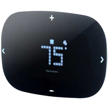
Product Picture


1 - Scale of temperature
Change the Unit of Temperature readingSize: 2 bytes
Default: 1
Minimum: 0
Maximum: 0
Possible values
| From | To | Desription |
|---|---|---|
| 0 | 1 |
2 - Swing
Swing Settings allows you to change the span on the temperature when your heating or cooling will kick in.Size: 2 bytes
Default: 2
Minimum: 0
Maximum: 0
Possible values
| From | To | Desription |
|---|---|---|
| 1 | 4 |
3 - Differential
Set the difference temperature between room temperature and target temperature where a second stage will turn on in a heater or compressor with multiple stage. Remark : ONLY for multiple stage systemSize: 2 bytes
Default: 2
Minimum: 0
Maximum: 0
Possible values
| From | To | Desription |
|---|---|---|
| 1 | 4 |
4 - Dead band
On thermostats that automatically control both heating and cooling systems, a dead band is a temperature range in which neither system turns on. The dead band prevents the thermostat from activating heat and cooling in rapid succession. This conserves energy by providing a range of temperatures requiring no energy consumptionSize: 2 bytes
Default: 4
Minimum: 0
Maximum: 0
Possible values
| From | To | Desription |
|---|---|---|
| 3 | 6 |
5 - Heat Set Point
Upper limit of Heat Set PointSize: 2 bytes
Default: 95
Minimum: 0
Maximum: 0
Possible values
| From | To | Desription |
|---|---|---|
| 41 | 99 | Fahrenheit unit |
6 - Cool Set Point
Lower limit of Cool Set PointSize: 2 bytes
Default: 45
Minimum: 0
Maximum: 0
Possible values
| From | To | Desription |
|---|---|---|
| 41 | 99 | Fahrenheit unit |
8 - Set Filter Counter
Set Filter Counter (in Hours)Size: 2 bytes
Default: 500
Minimum: 0
Maximum: 0
Possible values
| From | To | Desription |
|---|---|---|
| 500 | 4000 | Hours |
9 - Report Filter Counter
Read OnlySize: 2 bytes
Default: 0
Minimum: 0
Maximum: 0
Possible values
| From | To | Desription |
|---|---|---|
| 0 | 9999 | Hours |
10 - Sensor Temperature Calibration
Temperature Offset ValueSize: 2 bytes
Default: 0
Minimum: 0
Maximum: 0
Possible values
| From | To | Desription |
|---|---|---|
| 0 | 10 |
11 - LED Brightness Level
Set the LED Display Brightness LevelSize: 2 bytes
Default: 2
Minimum: 0
Maximum: 0
Possible values
| From | To | Desription |
|---|---|---|
| 1 | 3 |
12 - Sleep Timer
Set the Device Sleep Timer (in Seconds)Size: 2 bytes
Default: 5
Minimum: 0
Maximum: 0
Possible values
| From | To | Desription |
|---|---|---|
| 3 | 60 | Seconds |
13 - Repeat Basic Set Counter
Association Group A and B onlySize: 2 bytes
Default: 0
Minimum: 0
Maximum: 0
Possible values
| From | To | Desription |
|---|---|---|
| 3 | 255 | Minutes |
14 - Auto Report Room Temperature
Trigger AUTO report if room temperature is different from last report. (It will report room temperature only)Size: 2 bytes
Default: 1
Minimum: 0
Maximum: 0
Possible values
| From | To | Desription |
|---|---|---|
| 1 | 8 |
15 - Set Time Interval
AUTO report by time interval. (It will report room temperature only)Size: 2 bytes
Default: 0
Minimum: 0
Maximum: 0
Possible values
| From | To | Desription |
|---|---|---|
| 0 | 16 | Hours |
From the Standby screen, press > or < to navigate to the Z-Wave screen and the Z-Wave LED will continuously flash. Tap + to include the ZTS-500US into the network. - The “✔” symbol will be displayed on screen once the ZTS-500US is added into the network. The Z-Wave disconnect icon will also be removed from the standby screen. - The “x” symbol will be displayed on screen if there is no action (time out) or unable to include the ZTS-500US into the network.
Press and keep holding > or < for 3 seconds to navigate to the System Main (SYS) screen. On the Z-Wave (Z-w) screen. Tap + to exclude ZTS-500US from the network. Press < to cancel and back to the previous screen.
Press and keep holding > or < for 3 seconds to navigate to the System Main (SYS) screen. Press > to navigate to the Reset (RST) screen. Press + or - to select Yes. Press and keep holding > for 2 seconds to confirm your selection. Press < to cancel and back to the previous screen. Use the RESET procedure ONLY when the primary Controller is missing or inoperable.
| Type | Value(s) |
|---|