Z-Home Control
Wall Switch
ZHC5010
On/Off Power Switch
HW: 1 FW: 1.00
ZM5101
6.61.00
0x0234 (564)
0x0003 (3)
0x010A (266)
ZC10-16055065
2016-05-09 12:08:40.9334
N/A
Enhanced 232 Slave
Always On Slave
Wall switch module for FUGA® installations.
ZHC5010 is a wall switch module with four buttons, four LEDs, a built-in relay switch and is designed to fit into standard Danish LK FUGA® wall boxes.
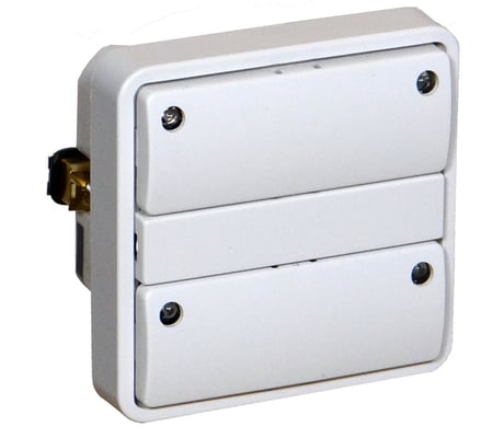
Product Picture


1 - Upper paddle buttons mode.
Configuration of Pair Mode for the upper two buttons (button #1 and #2).Size: 1 byte
Default: 0
Minimum: 0
Maximum: 0
Possible values
| From | To | Desription |
|---|---|---|
| 0 | 0 | Separate mode (toggle mode). |
| 1 | 1 | In pair mode, left side sends on/up commands, right side sends off/down commands. |
2 - Lower paddle buttons mode.
Configuration of Pair Mode for the lower two buttons (button #3 and #4).Size: 1 byte
Default: 0
Minimum: 0
Maximum: 0
Possible values
| From | To | Desription |
|---|---|---|
| 0 | 0 | Separate mode (toggle mode). |
| 1 | 1 | In pair mode, left side sends on/up commands, right side sends off/down commands. |
3 - LED #1 mode.
Configuration of the LED status indication.Size: 1 byte
Default: 1
Minimum: 0
Maximum: 0
Possible values
| From | To | Desription |
|---|---|---|
| 0 | 0 | LED indication is disabled (LED can be controlled by Indicator Command Class Set commands). |
| 1 | 1 | LED indicates the status of the corresponding button. |
| 2 | 2 | LED indicates the status of the corresponding button, with inverted indication. |
| 3 | 3 | LED indicates the status of corresponding paddle (in pair mode). |
| 4 | 4 | LED indicates the status of the corresponding paddle (in pair mode), with inverted indication. |
| 5 | 5 | LED indicates the status of the built-in relay. |
| 6 | 6 | LED indicates the status of the built-in relay, with inverted indication. |
| 7 | 7 | LED show a 5 seconds indication when the corresponding button is pressed. |
4 - LED #2 mode.
Configuration of the LED status indication.Size: 1 byte
Default: 1
Minimum: 0
Maximum: 0
Possible values
| From | To | Desription |
|---|---|---|
| 0 | 0 | LED indication is disabled (LED can be controlled by Indicator Command Class Set commands). |
| 1 | 1 | LED indicates the status of the corresponding button. |
| 2 | 2 | LED indicates the status of the corresponding button, with inverted indication. |
| 3 | 3 | LED indicates the status of corresponding paddle (in pair mode). |
| 4 | 4 | LED indicates the status of the corresponding paddle (in pair mode), with inverted indication. |
| 5 | 5 | LED indicates the status of the built-in relay. |
| 6 | 6 | LED indicates the status of the built-in relay, with inverted indication. |
| 7 | 7 | LED show a 5 seconds indication when the corresponding button is pressed. |
5 - LED #3 mode.
Configuration of the LED status indication.Size: 1 byte
Default: 1
Minimum: 0
Maximum: 0
Possible values
| From | To | Desription |
|---|---|---|
| 0 | 0 | LED indication is disabled (LED can be controlled by Indicator Command Class Set commands). |
| 1 | 1 | LED indicates the status of the corresponding button. |
| 2 | 2 | LED indicates the status of the corresponding button, with inverted indication. |
| 3 | 3 | LED indicates the status of corresponding paddle (in pair mode). |
| 4 | 4 | LED indicates the status of the corresponding paddle (in pair mode), with inverted indication. |
| 5 | 5 | LED indicates the status of the built-in relay. |
| 6 | 6 | LED indicates the status of the built-in relay, with inverted indication. |
| 7 | 7 | LED show a 5 seconds indication when the corresponding button is pressed. |
6 - LED #4 mode.
Configuration of the LED status indication.Size: 1 byte
Default: 1
Minimum: 0
Maximum: 0
Possible values
| From | To | Desription |
|---|---|---|
| 0 | 0 | LED indication is disabled (LED can be controlled by Indicator Command Class Set commands). |
| 1 | 1 | LED indicates the status of the corresponding button. |
| 2 | 2 | LED indicates the status of the corresponding button, with inverted indication. |
| 3 | 3 | LED indicates the status of corresponding paddle (in pair mode). |
| 4 | 4 | LED indicates the status of the corresponding paddle (in pair mode), with inverted indication. |
| 5 | 5 | LED indicates the status of the built-in relay. |
| 6 | 6 | LED indicates the status of the built-in relay, with inverted indication. |
| 7 | 7 | LED show a 5 seconds indication when the corresponding button is pressed. |
7 - LED #1 brightness level.
Configure the percentage of light in the LED, when the LED is turned on.Size: 1 byte
Default: 50
Minimum: 0
Maximum: 0
Possible values
| From | To | Desription |
|---|---|---|
| 0 | 100 | Specifies the brightness level of the LED when it is on. |
8 - LED #2 brightness level.
Configure the percentage of light in the LED, when the LED is turned on.Size: 1 byte
Default: 50
Minimum: 0
Maximum: 0
Possible values
| From | To | Desription |
|---|---|---|
| 0 | 100 | Specifies the brightness level of the LED when it is on. |
9 - LED #3 brightness level.
Configure the percentage of light in the LED, when the LED is turned on.Size: 1 byte
Default: 50
Minimum: 0
Maximum: 0
Possible values
| From | To | Desription |
|---|---|---|
| 0 | 100 | Specifies the brightness level of the LED when it is on. |
10 - LED #4 brightness level.
Configure the percentage of light in the LED, when the LED is turned on.Size: 1 byte
Default: 50
Minimum: 0
Maximum: 0
Possible values
| From | To | Desription |
|---|---|---|
| 0 | 100 | Specifies the brightness level of the LED when it is on. |
11 - LED #1 off brightness level.
Configure the percentage of light in the LED, when the LED is turned “off”.Size: 1 byte
Default: 0
Minimum: 0
Maximum: 0
Possible values
| From | To | Desription |
|---|---|---|
| 0 | 100 | Specifies the brightness level of the LED when it is off. |
12 - LED #2 off brightness level.
Configure the percentage of light in the LED, when the LED is turned “off”.Size: 1 byte
Default: 0
Minimum: 0
Maximum: 0
Possible values
| From | To | Desription |
|---|---|---|
| 0 | 100 | Specifies the brightness level of the LED when it is off. |
13 - LED #3 off brightness level.
Configure the percentage of light in the LED, when the LED is turned “off”.Size: 1 byte
Default: 0
Minimum: 0
Maximum: 0
Possible values
| From | To | Desription |
|---|---|---|
| 0 | 100 | Specifies the brightness level of the LED when it is off. |
14 - LED #4 off brightness level.
Configure the percentage of light in the LED, when the LED is turned “off”.Size: 1 byte
Default: 0
Minimum: 0
Maximum: 0
Possible values
| From | To | Desription |
|---|---|---|
| 0 | 100 | Specifies the brightness level of the LED when it is off. |
15 - Relay mode.
This parameter configures which of the buttons that shall control the built-in relay, or if the relay only will be activated for one second, each time button #1 is used.Size: 1 byte
Default: 1
Minimum: 0
Maximum: 0
Possible values
| From | To | Desription |
|---|---|---|
| 0 | 0 | Relay is disabled. |
| 1 | 1 | Relay is controlled by button #1 or by upper paddle when pair mode is active. |
| 2 | 2 | Relay is controlled by button #2 or by upper paddle when pair mode is active. |
| 3 | 3 | Relay is controlled by button #3 or by lower paddle when pair mode is active. |
| 4 | 4 | Relay is controlled by button #4 or by lower paddle when pair mode is active. |
| 5 | 5 | Relay is activated for one second and is controlled by button #1 or by upper paddle when pair mode is active. |
16 - Indicator mode.
When ZHC5010 receives an Indicator Set message, then the received value can be used only to set the current light level for the actual LED or the level value can be stored and will then be used for subsequent internal LED activations.Size: 1 byte
Default: 1
Minimum: 0
Maximum: 0
Possible values
| From | To | Desription |
|---|---|---|
| 0 | 0 | Indicator Set level values are only used to control the LED. |
| 1 | 1 | Indicator Set level values are also used by internal LED activations. |
17 - Scene notification offset.
Configure the scene sequence numbers that will be transmitted by Central Scene notifications.Size: 1 byte
Default: 1
Minimum: 0
Maximum: 0
Possible values
| From | To | Desription |
|---|---|---|
| 0 | 0 | Scene notifications are turned off. |
| 1 | 127 | Button #1 will send scene [value], button #2 will send scene [value] + 1, button #3 will send scene [value] + 2, button #4 will send scene [value] + 3. |
18 - Disable House Cleaning Mode.
This parameter is able to enable or disable the so-called “House Cleaning Mode”, where ZHC5010 is able to send a dimming command in order to set the level of the lights to 100%.Size: 1 byte
Default: 0
Minimum: 0
Maximum: 0
Possible values
| From | To | Desription |
|---|---|---|
| 0 | 0 | House Cleaning Mode is enabled. |
| 1 | 1 | House Cleaning Mode is disabled; double-press button scene notifications will be disabled too. |
23 - Control of association groups for device 1 (button #1)
Enable or disable if received commands are relayed to the nodes in the association groups.Size: 1 byte
Default: 1
Minimum: 0
Maximum: 0
Possible values
| From | To | Desription |
|---|---|---|
| 0 | 0 | When commands are received by device 1, nodes in the association groups will not be switched, button activations will still send switch values. |
| 1 | 1 | When commands are received by device 1, nodes in the association groups will be switched. |
24 - Control of association groups for device 2 (button #2)
Enable or disable if received commands are relayed to the nodes in the association groups.Size: 1 byte
Default: 1
Minimum: 0
Maximum: 0
Possible values
| From | To | Desription |
|---|---|---|
| 0 | 0 | When commands are received by device 2, nodes in the association groups will not be switched, button activations will still send switch values. |
| 1 | 1 | When commands are received by device 2, nodes in the association groups will be switched. |
25 - Control of association groups for device 3 (button #3)
Enable or disable if received commands are relayed to the nodes in the association groups.Size: 1 byte
Default: 1
Minimum: 0
Maximum: 0
Possible values
| From | To | Desription |
|---|---|---|
| 0 | 0 | When commands are received by device 3, nodes in the association groups will not be switched, button activations will still send switch values. |
| 1 | 1 | When commands are received by device 3, nodes in the association groups will be switched. |
26 - Control of association groups for device 4 (button #4)
Enable or disable if received commands are relayed to the nodes in the association groups.Size: 1 byte
Default: 1
Minimum: 0
Maximum: 0
Possible values
| From | To | Desription |
|---|---|---|
| 0 | 0 | When commands are received by device 4, nodes in the association groups will not be switched, button activations will still send switch values. |
| 1 | 1 | When commands are received by device 4, nodes in the association groups will be switched. |
Pushing the upper left button 3 times, (triple click) will activate Inclusion Mode on the device. It is also possible to activate Inclusion Mode by triple clicking the switch in the middle of the module (normally covered by the middle plastic cover, this can be removed by means of a little screwdriver).
Pushing the upper left button 3 times, (triple click) will activate Exclusion Mode on the device. It is also possible to activate Exclusion Mode by triple clicking the switch in the middle of the module (normally covered by the middle plastic cover, this can be removed by means of a little screwdriver).
ZHC5010 can be factory reset by pressing the small button in the middle of the module (normally covered by small plastic cover) for at least 10 seconds. Please use this procedure only when the network primary controller is missing or otherwise inoperable.