Winytechnology
Wall Switch
WTR-1210-11
On/Off Power Switch
1.01
ZM5101
6.51.06
0x0242 (578)
0x0003 (3)
0x0012 (18)
ZC10-16080001
2016-08-02 00:08:50.238
N/A
Enhanced 232 Slave
N/A
Z-Wave Wall Switch provides on/off control of a light by smartphone or manual.
Z-Wave Wall Switch provides on/off control of a light by smartphone or manual. Adds local and Z-Wave On/Off control to a wired light or appliance and can replace a traditional On/Off switch.
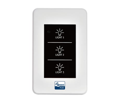
Product Picture


2 - Automatic Key Report Control (AKRC)
This option determines when the reporting of the key is performed, at press or at release.Size: 1 byte
Default: 1
Minimum: 0
Maximum: 0
Possible values
| From | To | Desription |
|---|---|---|
| 0 | 0 | Release report set at the press of a button |
| 1 | 1 | Report at the press of a button |
3 - Control Relay Select (CRS)
This option determines which relay will be controlled. This option is set using a bit mask, which means that the values indicated below can be added together to select multiple relays.Size: 1 byte
Default: 15
Minimum: 0
Maximum: 0
Possible values
| From | To | Desription |
|---|---|---|
| 1 | 1 | Control Relay 1 |
| 2 | 2 | Control Relay 2 |
| 3 | 3 | Control Relay 3 |
| 15 | 15 | Control Relay Full |
101 - Key Report Source Select (KRSS)
This option sets which keys will report. The option is a bit mask option, so values should be added together of multiple keys are being selected. For example, 1 + 4 = 5 turns on reporting for Key 1 and Key 3.Size: 4 bytes
Default: 1792
Minimum: 0
Maximum: 0
Possible values
| From | To | Desription |
|---|---|---|
| 1 | 1 | Key 1 Report |
| 2 | 2 | Key 2 Report |
| 4 | 4 | Key 3 Report |
255 - Reset
Initialize a select configuration parameter, or reset all configuration parameters to their default values.Size: 1 byte
Default: 255
Minimum: 0
Maximum: 0
Possible values
| From | To | Desription |
|---|---|---|
| 2 | 2 | Initialize Parameter 2 to default |
| 3 | 3 | Initialize Parameter 3 to default |
| 101 | 101 | Initialize Parameter 101 to default |
| 255 | 255 | Reset to the default full Parameter |
A. Confirm that a device must be wireless access to Z-Wave network. (Fn Display: Green LED OFF) B. Set “NW Inclusion” or “Node Add” by controller. C. Press Fn switch 3 times in a row to include the device to Z-Wave network. (Fn Display: Green LED blinking) D. Confirm that a device is included on Z-Wave network. (Fn Display: Green LED blinking)
A. Confirm that a device is included on Z-Wave network. (Fn Display: Green LED blinking) B. Set “Node remove” by controller. C. Press Fn switch 3 times in a row to cancel the incluion on Z-Wave network. (Fn Display: Red LED blinking) If the controller is not on “Node remove” status, device will automatically cancel “Exclusion”. (Fn Display: Green LED ON) D. Confirm that it remove the device from Z-Wave network. (Fn Display Green LED - OFF)
Use this procedure only in the event that the network primary controller is missing or otherwise inoperable. Press Fn switch over 10~15 sec to initialize connecting network information.
| Type | Value(s) |
|---|