FortrezZ LLC
MIMO2+
MIMO2+
Multilevel Sensor
HW: 5 FW: 2.08
ZM5202
6.51.08
0x0084 (132)
0x0463 (1123)
0x0204 (516)
ZC10-16075155
2016-07-29 10:31:32.319
N/A
Enhanced 232 Slave
Always On Slave
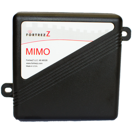
MIMO2+ Multiple Input - Multiple Output Module is an interface / bridge module that has two voltage inputs and two dry contact relays.
The MIMO2+ module provides two voltage inputs and two relay outputs (either can be wired normally open or normally closed). Z-Wave™ messages can be used to read the inputs and control the outputs. The inputs are very configurable for different trigger conditions and can even be mapped to control the outputs. The module includes a button for Z-Wave™ inclusion/exclusion and an LED for various status indications. The functionality of the SIG1 and SIG2 inputs is: - Analog Triggering: Various trigger conditions can be set for high-to-low and low-to-high transitions. This provides great flexibility for capturing digital or analog events in a wide variety of applications. The trigger status can be automatically sent to the controller. - Associations: Each input can be associated with up to two other Z-Wave™ devices, so that, for example, an associated device will automatically turn on (or off) based on the occurrence of a trigger event. Voltage Reporting: The analog input voltage levels can also be sent to the controller. The physical outputs are relays that are typically activated by Z-Wave™ commands. However, the user can override Z-Wave™ control by configuring the input trigger conditions to be mapped to the output relays via logical AND/OR functions.


1 - Relay 1 Configuration
This sets the configuration of Relay 1 to be latching, or to toggle back to Off/Open after a specified amount of time. (Signed value in the range 0 to 255; convert values over 127 to a signed 1 byte value, or if your controller supports entering the value in hexadecimal you may use the hex value.)Size: 1 byte
Default: 0
Minimum: 0
Maximum: 0
Possible values
| From | To | Desription |
|---|---|---|
| 0 | 0 | The relay will remain latched in the position it is commanded to (open/off or closed/on) |
| -128 | 127 | Set this value to the amount of time in 100ms increments for the relay to remain closed/on before automatically returning to the open/off state. For example, a value of 2 = 0.2 Seconds. |
2 - Relay 2 Configuration
This sets the configuration of Relay 2 to be latching, or to toggle back to Off/Open after a specified amount of time. (Signed value in the range 0 to 255; convert values over 127 to a signed 1 byte value, or if your controller supports entering the value in hexadecimal you may use the hex value.)Size: 1 byte
Default: 5
Minimum: 0
Maximum: 0
Possible values
| From | To | Desription |
|---|---|---|
| 0 | 0 | The relay will remain latched in the position it is commanded to (open/off or closed/on) |
| -128 | 127 | Set this value to the amount of time in 100ms increments for the relay to remain closed/on before automatically returning to the open/off state. For example, a value of 2 = 0.2 Seconds. |
3 - SIG 1 Multilevel Trigger Settings
b7: Trigger Between Thresholds (1=true) b6: Periodic Sends (=0) or Send when Change-of-Trigger (=1) b5-b0: Periodic Send Interval for Lifeline (30s resolution, 0=no periodic sends) Reference technical appendix triggering notes for visual's. (Signed value in the range 0 to 255; convert values over 127 to a signed 1 byte value, or if your controller supports entering the value in hexadecimal you may use the hex value.)Size: 1 byte
Default: -88
Minimum: 0
Maximum: 0
Possible values
| From | To | Desription |
|---|---|---|
| -128 | 127 | Set this value to trigger between thresholds |
4 - SIG 1 Lower Threshold, High
(must be less than Upper Threshold Low and greater than Lower Threshold Low) Reference technical appendix triggering notes for visual's. (Signed value in the range 0 to 255; convert values over 127 to a signed 1 byte value, or if your controller supports entering the value in hexadecimal you may use the hex value.)Size: 1 byte
Default: -112
Minimum: 0
Maximum: 0
Possible values
| From | To | Desription |
|---|---|---|
| -128 | 127 | Set this value to set the lower threshold high number |
5 - SIG 1 Lower Threshold, Low
SIG 1 Lower Threshold, Low Reference technical appendix triggering notes for visual's. (Signed value in the range 0 to 255; convert values over 127 to a signed 1 byte value, or if your controller supports entering the value in hexadecimal you may use the hex value.)Size: 1 byte
Default: -128
Minimum: 0
Maximum: 0
Possible values
| From | To | Desription |
|---|---|---|
| -128 | 127 | Set this to set the lower threshold low number. |
6 - SIG 1 Upper Threshold, High
SIG1 Upper Threshold, High Use this to set the upper threshold High number. Reference technical appendix triggering notes for visual's. (Signed value in the range 0 to 255; convert values over 127 to a signed 1 byte value, or if your controller supports entering the value in hexadecimal you may use the hex value.)Size: 1 byte
Default: -1
Minimum: 0
Maximum: 0
Possible values
| From | To | Desription |
|---|---|---|
| -128 | 127 | Set this to set the upper threshold, high number |
7 - SIG 1 Upper Threshold, Low
(Must be greater than lower Threshold High and less than Upper Threshold High) Reference technical appendix triggering notes for visual's. (Signed value in the range 0 to 255; convert values over 127 to a signed 1 byte value, or if your controller supports entering the value in hexadecimal you may use the hex value.)Size: 1 byte
Default: -2
Minimum: 0
Maximum: 0
Possible values
| From | To | Desription |
|---|---|---|
| -128 | 127 | Set this to set the upper threshold low number |
9 - SIG 2 Multilevel Trigger Settings
b7: Trigger Between Thresholds (1=true) b6: Periodic Sends (=0) or Send when Change-of-Trigger (=1) b5-b0: Periodic Send Interval for Lifeline (30s resolution, 0=no periodic sends) Reference technical appendix triggering notes for visual's. (Signed value in the range 0 to 255; convert values over 127 to a signed 1 byte value, or if your controller supports entering the value in hexadecimal you may use the hex value.)Size: 1 byte
Default: -88
Minimum: 0
Maximum: 0
Possible values
| From | To | Desription |
|---|---|---|
| -128 | 127 | Set this value to trigger between thresholds |
10 - SIG 2 Lower Threshold, High
(must be less than Upper Threshold Low and greater than Lower Threshold Low) Reference technical appendix triggering notes for visual's. (Signed value in the range 0 to 255; convert values over 127 to a signed 1 byte value, or if your controller supports entering the value in hexadecimal you may use the hex value.)Size: 1 byte
Default: -112
Minimum: 0
Maximum: 0
Possible values
| From | To | Desription |
|---|---|---|
| -128 | 127 | Set this value to set the lower threshold high number |
11 - SIG 2 Lower Threshold, Low
SIG 2 Lower Threshold, Low Reference technical appendix triggering notes for visual's. (Signed value in the range 0 to 255; convert values over 127 to a signed 1 byte value, or if your controller supports entering the value in hexadecimal you may use the hex value.)Size: 1 byte
Default: -128
Minimum: 0
Maximum: 0
Possible values
| From | To | Desription |
|---|---|---|
| -128 | 127 | Set this to set the lower threshold low number. |
12 - SIG 2 Upper Threshold, High
SIG 2 Upper Threshold, High Reference technical appendix triggering notes for visual's. (Signed value in the range 0 to 255; convert values over 127 to a signed 1 byte value, or if your controller supports entering the value in hexadecimal you may use the hex value.)Size: 1 byte
Default: -1
Minimum: 0
Maximum: 0
Possible values
| From | To | Desription |
|---|---|---|
| -128 | 127 | Set this to set the upper threshold, high number |
13 - SIG 2 Upper Threshold, Low
(Must be greater than lower Threshold High and less than Upper Threshold High) Reference technical appendix triggering notes for visual's. (Signed value in the range 0 to 255; convert values over 127 to a signed 1 byte value, or if your controller supports entering the value in hexadecimal you may use the hex value.)Size: 1 byte
Default: -2
Minimum: 0
Maximum: 0
Possible values
| From | To | Desription |
|---|---|---|
| -128 | 127 | Set this to set the upper threshold low number |
1) Activate inclusion mode on your Z-wave controller. 2) Press the program button once. 3) LED will blink 2 times quickly to indicate ""in network"" status.
1) Activate exclusion mode on your Z-wave controller. 2) Press the program button once. 3) LED will blink 4 times quickly to indicate ""in network"" status.
Device Reset to Factory Defaults – Press and hold the program button for 15 seconds and then release. This can be done while the device is either in or out of a network. CAUTION – When this is done in-network, the device will no longer be in the network and all configurations and associations will be set to default. Please use this procedure only when your network primary controller is missing or otherwise inoperable.
To configure Relay's for Momentary or Latched function, the configuration command class is used. Refer to Technical appendix document to instructions. This and all documents are available for download at fortrezz.com
| Type | Value(s) |
|---|
| Sensor type |
|---|
| General Purpose |