NodOn
OCTAN Remote
CRC-3-1-0X
Remote Control - Multi Purpose
HW: 2 FW: 3.03:01.05
ZM5202
6.51.06
0x0165 (357)
0x0002 (2)
0x0001 (1)
ZC10-16085200
2016-08-30 11:34:10.796604
N/A
Portable Controller
Portable Controller
Yes
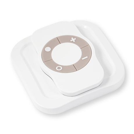
The OCTAN Remote NodOn® controls any compatible receivers Z-Wave® or Z-Wave Plus®. It can address, directly, up to 4 groups of 8 devices and sent up to 16 different scenes to a Home Automation Gateway.
The OCTAN Remote NodOn® controls any compatible receivers Z-Wave® or Z-Wave Plus®, such as the Smart Plug NodOn®. It can address, directly, up to 4 groups of 8 devices and sent up to 16 different scenes to a Home Automation Gateway. This controller can operate on its own (“Standalone” Mode) or as gateway’s assistant (“Gateway” Mode). The product integrates a LED, which give an intuitive feedback for each operation you perform. Based on an innovative technology, the OCTAN Remote NodOn® is only powered with a CR2032 battery, offering 2 years’ autonomy. A magnetic wall support is included with your OCTAN Remote NodOn®, which allow you to easily install and move it. This support can be screwed or fixed by adhesive bonding. The remote control embeds a small magnet, allowing fixing it on its wall support or on any metallic surface (fridge door, heater, etc.). The OCTAN Remote NodOn® is based on brand new 500 series Z-Wave® module from Sigma Designs®, and supports all the new features of Z-Wave Plus® standard: Longer range (up to 40 meters indoor), lower power consumption, higher data rate transmission, and many more new features.


1 - Buttons 1&3 Profile
This parameter configures the behavior of the buttons 1 and 3 when the product is in “Gateway" Mode.Size: 1 byte
Default: 0
Minimum: 0
Maximum: 0
Possible values
| From | To | Desription |
|---|---|---|
| 0 | 0 | SCENE. Product sends “Central Scene Notification” Commands or “Scene Activation” Commands. |
| 1 | 1 | MONO. Button 1 is not paired with button 3. |
| 2 | 2 | DUO. Button 1 is paired with button 3. |
2 - Buttons 2&4 Profile
This parameter configures the behavior of the buttons 2 and 4 when the product is in “Gateway" Mode.Size: 1 byte
Default: 0
Minimum: 0
Maximum: 0
Possible values
| From | To | Desription |
|---|---|---|
| 0 | 0 | SCENE. Product sends “Central Scene Notification” Commands or “Scene Activation” Commands. |
| 1 | 1 | MONO. Button 1 is not paired with button 3. |
| 2 | 2 | DUO. Button 1 is paired with button 3. |
3 - Scene Type
This parameter configures the type of command sent when the product is in “Gateway Centric Mode”, with buttons profile configuration set in SCENE. We strongly advise you to use « CENTRAL SCENE », which is more user friendly. However, some home automation gateways don’t support « CENTRAL SCENE » yet, then you can still use the previous standard « SCENE ACTIVATION ». The user interface of your gateway will then allow you to set-up scenes. Note: If Parameter N°1 or N°2 is not set in SCENE, then this parameter is ignored.Size: 1 byte
Default: 0
Minimum: 0
Maximum: 0
Possible values
| From | To | Desription |
|---|---|---|
| 0 | 0 | Use “CENTRAL SCENE” Commands. |
| 1 | 1 | Use “SCENE ACTIVATION” Commands. |
4 - Button 1 Configuration
This parameter configures the behavior of the button 1 in “Gateway" Mode, when set in MONO (refers Parameter N°1 – Buttons 1&3 Profile) Note: If Parameter N°1 is not set in MONO, then this parameter is ignored.Size: 1 byte
Default: 0
Minimum: 0
Maximum: 0
Possible values
| From | To | Desription |
|---|---|---|
| 0 | 0 | Single Press sends “Basic Set” Command to associated devices in Group 2. |
| 1 | 1 | Single Press sends broadcast “Switch All On” Command. |
| 2 | 2 | Single Press sends broadcast “Switch All Off” Command. |
5 - Button 2 Configuration
This parameter configures the behavior of the button 2 in “Gateway" Mode, when set in MONO (refers Parameter N°1 – Buttons 2&4 Profile) Note: If Parameter N°2 is not set in MONO, then this parameter is ignored.Size: 1 byte
Default: 0
Minimum: 0
Maximum: 0
Possible values
| From | To | Desription |
|---|---|---|
| 0 | 0 | Single Press sends “Basic Set” Command to associated devices in Group 3. |
| 1 | 1 | Single Press sends broadcast “Switch All On” Command. |
| 2 | 2 | Single Press sends broadcast “Switch All Off” Command. |
6 - Button 3 Configuration
This parameter configures the behavior of the button 3 in “Gateway" Mode, when set in MONO (refers Parameter N°1 – Buttons 1&3 Profile) Note: If Parameter N°1 is not set in MONO, then this parameter is ignored.Size: 1 byte
Default: 0
Minimum: 0
Maximum: 0
Possible values
| From | To | Desription |
|---|---|---|
| 0 | 0 | Single Press sends “Basic Set” Command to associated devices in Group 4. |
| 1 | 1 | Single Press sends broadcast “Switch All On” Command. |
| 2 | 2 | Single Press sends broadcast “Switch All Off” Command. |
7 - Button 4 Configuration
This parameter configures the behavior of the button 4 in “Gateway" Mode, when set in MONO (refers Parameter N°1 – Buttons 2&4 Profile) Note: If Parameter N°2 is not set in MONO, then this parameter is ignored.Size: 1 byte
Default: 0
Minimum: 0
Maximum: 0
Possible values
| From | To | Desription |
|---|---|---|
| 0 | 0 | Single Press sends “Basic Set” Command to associated devices in Group 5. |
| 1 | 1 | Single Press sends broadcast “Switch All On” Command. |
| 2 | 2 | Single Press sends broadcast “Switch All Off” Command. |
8 - Led Management
This parameter configures the behavior of the Led in "Gateway" Mode.Size: 1 byte
Default: 0
Minimum: 0
Maximum: 0
Possible values
| From | To | Desription |
|---|---|---|
| 0 | 0 | Led does not acknowledge button action and does not acknowledge result of radio command sent. |
| 1 | 1 | When the end-user performs a Single press, Double press or Hold Press on a button, led blinks blue to acknowledge the button action. |
| 2 | 2 | When the end-user sends a controlled command: “Basic Set” Command “Central Scene Notification” Command “Multilevel Switch Stop Level Change” Command Led blinks GREEN to acknowledge transmission success or blinks RED to acknowledge transmission failed. |
| 3 | 3 | Combined behaviors of 0x01 and 0x02 modes. |
1- Place your home automation gateway into “Inclusion” Mode. To do so, please refer to your gateway’s user guide. 2- Simultaneously push on buttons 1 and 2, during 1 second. The LED glows in pink to confirm the selection. 3- Push on button 1. The LED blinks in pink to confirm your choice. 4- The LED blinks in green to confirm the procedure
When the product in ""Gateway"" mode, any action on button will send a wake up notification to the gateway.
Simultaneously push on buttons 3 and 4, during 1 second. The LED will blink red and green to validate the factory reset. A factory reset will completely delete the memory of the remote control and restore all parameters to default value. In ""Standalone"" Mode, make sure to remove all the devices added or associated in the remote control's network before performing a factory reset. In ""Gateway"" Mode, use the factory reset procedure only when the primary controller (i.e the Gateway) is missing or defective. Reset the remote control does not mean that it has been removed from the primary controller memory. Remove the remote control (through the primary controller) before performing a factory reset.
Association, in ""Standalone"" mode is performed in 3 steps: 1- Push 3 times (quickly) on the button 1 to activate the ""Association” Mode. The LED glows in blue. 2- Choose which button will control your device. • A short press on one of the buttons of the remote control (1, 2, 3 or 4) will activate the MONO Profile. The pressed button will then control your device. • A long press on the button 1 will activate the DUO Profile, combined with the button 3. The button 1 (ON) and button 3 (OFF) will then control your device. • A long press on the button 2 will activate the DUO Profile, combined with the button 3. The button 2 (ON) and button 4 (OFF) will then control your device. The LED blinks in blue to confirm your choice. 3-Place the device you want to associate in “Learning” Mode. To do so, please refer to your device’s user guide. The LED of the remote control blinks green to confirm the association process Careful: In case of a too long association process or others problems during the process, the LED will blink red (Timeout). Please restart the procedure. Once the association is validated, your remote control is able to control your device. Different actions are possible.
1- Push 3 times (quickly) on the button 1. The LED blinks in blue. 2- Place the device you want to add in ""Learning"" Mode, within 10 seconds. To do so, please refer to your device's user guide. 3- The LED blinks in green to confirm the inclusion.
1- Push 3 times (quickly) on the button 4. The LED blinks in blue. 2- Place the device you want to remove in ""Learning"" Mode, within 10 seconds. To do so, please refer to your device's user guide. 3- The LED blinks in green to confirm the exclusion.
| Type | Value(s) |
|---|