Seco srl
Wireless Energy Meter
SYS-72027-ENL/01
Whole Home Meter - Simple
HW: 1 FW: 1.01:00.07
ZM5202
6.61.00
0x0301 (769)
0x0048 (72)
0x010F (271)
ZC10-17115826
2017-10-31 20:35:29.418995
N/A
Routing Slave
Always On Slave
The Wireless Energy Meter performs real-time measurement of power, energy, voltage, and current, and transmits them wirelessly to a central controller.
The Wireless Energy Meter (WEM) is a smart device that performs quasi real-time measurements of the electricity consumption of the home by continuously monitoring the power line. WEM will be installed into the main distribution board, with the amperometric clamp closed around the live wire of a 1-phase system. This allows WEM to measure the line voltage and current, and thus compute the total power and energy consumption of the home. After a simple configuration phase, WEM starts reporting the measurement it takes to a central controller device, such as a home gateway, by means of the Z-Wave wireless technology. Z-Wave is a widespread and interoperable wireless home control technology based on the ITU-T 9959 open standard. WEM has an intuitive user interface, with a LED informing the user about its current state, and a push button to let the user issue the necessary commands. WEM can measure and report the following physical dimensions: Total Accumulated Active Energy (Wh), Instantaneous Active Power (W), RMS Voltage (V), RMS Current (A). WEM allows to fine-tune the way the measurements are performed and reported by means of several parameters, which can be set by most controllers on the market.
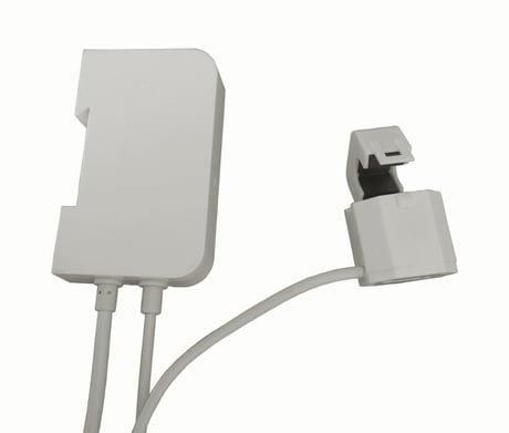
Product Picture


2 - Meas_Period
Meas_Period is the unit period for computing a measurement. WEM checks for changes in the line measures every Meas_Period. If there are meaningful changes, a report is sent to the controller. Therefore Meas_Period also represents represents the minimum reporting interval, i.e. 1/Meas_Period is the maximum reporting frequency.Size: 1 byte
Default: 30
Minimum: 0
Maximum: 0
Possible values
| From | To | Desription |
|---|---|---|
| 30 | 120 | seconds |
3 - Max_Rep_Interval
Max_Rep_Interval is the maximum time that can elapse without sending a report. If no meaningful events occur, WEM sends one full measurement every Max_Rep_Interval seconds.Size: 1 byte
Default: 6
Minimum: 0
Maximum: 0
Possible values
| From | To | Desription |
|---|---|---|
| 3 | 60 | seconds x 10 |
4 - Res_Active_Power
Res_Active_Power is the minimum quantity (resolution) that triggers a report for active power. It can be used to tune the sensitivity of WEM to changes in this physical dimension.Size: 1 byte
Default: 4
Minimum: 0
Maximum: 0
Possible values
| From | To | Desription |
|---|---|---|
| 1 | 100 | Watt |
5 - Res_RMS_Voltage
Res_RMS_Voltage is the minimum quantity (resolution) that triggers a report for active power. It can be used to tune the sensitivity of WEM to changes in this physical dimension.Size: 2 bytes
Default: 10
Minimum: 0
Maximum: 0
Possible values
| From | To | Desription |
|---|---|---|
| 1 | 1000 | Volt x 0.1 |
6 - Res_RMS_Current
Res_RMS_Current is the minimum quantity (resolution) that triggers a report for active power. It can be used to tune the sensitivity of WEM to changes in this physical dimension.Size: 2 bytes
Default: 10
Minimum: 0
Maximum: 0
Possible values
| From | To | Desription |
|---|---|---|
| 1 | 1000 | Ampere x 0.01 |
8 - Clamp_reversed
Clamp_Reversed is a read-only parameter that the controller can query to learn about the current placement of the clamp. During the measurement phase, WEM checks whether the clamp has been placed correctly or reversed (with regard to phase rotation). In the latter case, WEM notifies the user with a different blink pattern and stores this information into the Clamp_Reversed parameter. The clamp is placed correctly if Clamp_Reversed = 0 and is reversed if Clamp_Reversed = 1. If Clamp_Reversed = 0xFF a fault occurred and it was not possible to detect the clamp position.Size: 1 byte
Default: 255
Minimum: 0
Maximum: 0
Possible values
| From | To | Desription |
|---|---|---|
| 0 | 255 | only 0,1, 255 (0xFF) are valid |
9 - Enable_CRC16
Enable_CRC16 provides for an extra layer of redundancy in order to protect low bit rate transmissions against radio channel errors. This applies to the reports and frames sent spontaneous by WEM. Requests from the controller are always answered as asked. WEM will send CRC16 encapsulated frames to the associated node if this has proved to support it and Enable_CRC16 is set to 1. Otherwise, reports will be sent with no extra CRC16 encapsulation.Size: 1 byte
Default: 1
Minimum: 0
Maximum: 0
Possible values
| From | To | Desription |
|---|---|---|
| 0 | 1 |
10 - Avg_Period
Avg_Period determines the time window used to compute an average over the line readings. Each unit of Avg_Period is worth 5 seconds. If Avg_Period = 0 no average is computed and the last sample is returned. Note that the maximum average window coincides with the minimum value of Max_Rep_Interval. Also note that a delay of up to the average window can be introduced in returning the measurements (each measurement is returned only when ready).Size: 1 byte
Default: 1
Minimum: 0
Maximum: 0
Possible values
| From | To | Desription |
|---|---|---|
| 0 | 6 | seconds x 5 |
Once WEM is installed and connected to the power line for the first time, it goes into the “Idle” state. To add WEM to the Z-Wave network, it is first necessary to put the primary Z-Wave controller into inclusion mode (refer to the controller user manual). Then, press the WEM button for about 1 second. WEM enters the “Learning” state and the LED changes blinking pattern. When the learning phase ends successfully, WEM enters the “Synchronizing” state, and then the “Joined, Comm. Ok” state. If the clamp is not placed correctly, the “Joined, Clamp Rev.” state is entered in place of the “Joined, Comm. Ok” one. If the inclusion fails, WEM goes back to the “Idle” state.
To remove WEM from the network, it is first necessary to put the primary Z-Wave controller into exclusion mode (refer to the controller user manual). Then, press the WEM button for about 3 seconds. WEM enters the “Leaving” state, and waits for the controller to acknowledge its exclusion. When the exclusion process is complete, WEM goes into the “Idle” state. If the exclusion process fails, WEM goes back to its previous state.
WEM can be reset to the factory default values at any time by pressing the button for about 10 seconds, until the LED turns steadily on. WEM performs the reset operations and the button can be released. When the reset is complete, WEM enters the “Idle” state. Note that this reset procedure does not remove WEM from a classic Z-Wave controller or in situations where WEM cannot communicate with the Z-Wave Plus controller. Therefore this procedure should be used only when the primary controller is missing or inoperable. To remove WEM from the network under normal circumstances the exclusion procedure should be used.
| Type | Value(s) |
|---|
| Meter type |
|---|
| Electric Meter Consumption |