Aeotec
Nano Dimmer
ZW111-B
Light Dimmer Switch
HW: 111 FW: 1.01:01.01
ZM5101
6.51.09
0x0086 (134)
0x0203 (515)
0x006F (111)
ZC10-17015387
2016-12-26 20:48:56.070834
N/A
Enhanced 232 Slave
Always On Slave
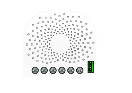
Aeotec Nano Dimmer is a Z-Wave Smart Dimmer specifically used to enable Z-Wave command and control (on/off/dim) of any wall switches also provides energy metering.
Aeotec Nano Dimmer is a Z-Wave Smart Dimmer specifically used to enable Z-Wave command and control (on/off/dim) of any wall switches. It can report immediate wattage consumption or kWh energy usage over a period of time. In the event of power failure, non-volatile memory retains all programmed information relating to the unit’s operating status. It can connect to 2 external manual switches to control the load ON/OFF independently. Its surface has a pin socket, which can be used for connecting to the touch panel, so you can also use the touch panel to control the Nano Dimmer. The Nano Dimmer is also a security Z-Wave plus device and supports Over The Air (OTA) feature for the products firmware upgrade.


3 - Current Overload Protection.
Output Load will be turned off automatically after 30 seconds and if the current overrun 1.5A.Size: 1 byte
Default: 1
Minimum: 0
Maximum: 0
Possible values
| From | To | Desription |
|---|---|---|
| 1 | 1 | Enable |
| 0 | 0 | Disable |
4 - Overheat protection.
Output Load will be turned off automatically after 30 seconds and if the temperature of product inside exceeds 100 ℃.Size: 1 byte
Default: 0
Minimum: 0
Maximum: 0
Possible values
| From | To | Desription |
|---|---|---|
| 0 | 0 | Disable |
| 1 | 1 | Enable |
20 - Configure the output status after re-power on it.
Configure the output status after re-power on it.Size: 1 byte
Default: 0
Minimum: 0
Maximum: 0
Possible values
| From | To | Desription |
|---|---|---|
| 0 | 0 | Last status |
| 2 | 2 | Always off |
| 1 | 1 | Always on |
80 - To set which notification would be sent to the associated devices (Group 1)
To set which notification would be sent to the associated devices (Group 1) when the state of Nano Dimmer’s load is changed.Size: 1 byte
Default: 0
Minimum: 0
Maximum: 0
Possible values
| From | To | Desription |
|---|---|---|
| 1 | 1 | Send Hail CC |
| 2 | 2 | Send Basic CC report |
| 3 | 3 | Send Multilevel Switch report |
| 0 | 0 | Send Nothing |
| 4 | 4 | Send Hail CC when using the manual switch to change the load state. |
81 - To set which notification would be sent to the associated nodes in association group 3
To set which notification would be sent to the associated nodes in association Group 3 when using the external switch 1 to switch the loads.Size: 1 byte
Default: 1
Minimum: 0
Maximum: 0
Possible values
| From | To | Desription |
|---|---|---|
| 1 | 1 | Send Basic Set CC |
| 0 | 0 | Send Nothing |
82 - To set which notification would be sent to the associated nodes in association group 4
To set which notification would be sent to the associated nodes in association Group 4 when using the external switch 2 to switch the loads.Size: 1 byte
Default: 1
Minimum: 0
Maximum: 0
Possible values
| From | To | Desription |
|---|---|---|
| 0 | 0 | Send Nothing |
| 1 | 1 | Send Basic Set CC |
85 - Set appointment 1
Set the ON time of output load.Size: 4 bytes
Default: 1573017
Minimum: 0
Maximum: 0
Possible values
| From | To | Desription |
|---|---|---|
| 16777215 | 16777222 | The day value (Mon to Sun) |
| 256 | 316 | The minute value of ON time |
| 65536 | 65560 | The hour value of ON time |
| 0 | 99 | The brightness level |
86 - Set appointment 2
Set the ON time of output load.Size: 4 bytes
Default: 2293760
Minimum: 0
Maximum: 0
Possible values
| From | To | Desription |
|---|---|---|
| 0 | 99 | The brightness level |
| 256 | 316 | The minute value of ON time |
| 65536 | 65560 | The hour value of ON time |
| 16777215 | 16777222 | The day value (Mon to Sun) |
90 - Enables/disables parameter 91 and 92 below:
Enables/disables the function of parameter 91 and 92.Size: 1 byte
Default: 0
Minimum: 0
Maximum: 0
Possible values
| From | To | Desription |
|---|---|---|
| 0 | 0 | Disable |
| 1 | 1 | Enable |
91 - Set the threshold value of wattage.
Threshold change in wattage (in terms of wattage) to induce an automatic report.Size: 2 bytes
Default: 25
Minimum: 0
Maximum: 0
Possible values
| From | To | Desription |
|---|---|---|
| 0 | 60000 | The thershold value range is 0 to 60000 |
92 - Set the threshold value of wattage.
Threshold change in wattage (in terms of percentage) to induce an automatic report.Size: 1 byte
Default: 5
Minimum: 0
Maximum: 0
Possible values
| From | To | Desription |
|---|---|---|
| 0 | 100 | The thershold value range is 0 to 100 |
100 - Set parameter 101-103 to default value.
Set parameter 101-103 to default value.Size: 1 byte
Default: 0
Minimum: 0
Maximum: 0
Possible values
| From | To | Desription |
|---|---|---|
| 0 | 0 | Reset the parameter 101-103 |
101 - To set which reports need to be sent in Report group 1.
To set which reports need to be sent in Report group 1.Size: 4 bytes
Default: 0
Minimum: 0
Maximum: 0
Possible values
| From | To | Desription |
|---|---|---|
| 1 | 1 | Send Meter Report of voltage (V) |
| 2 | 2 | Send Meter Report of current (A) |
| 4 | 4 | Send Meter Report of wattage (W) |
| 8 | 8 | Send Meter Report of energy (kWh) |
102 - To set which reports need to be sent in Report group 2.
To set which reports need to be sent in Report group 2.Size: 1 byte
Default: 0
Minimum: 0
Maximum: 0
Possible values
| From | To | Desription |
|---|---|---|
| 1 | 1 | Send Meter Report of voltage (V) |
| 2 | 2 | Send Meter Report of current (A) |
| 4 | 4 | Send Meter Report of wattage (W) |
| 8 | 8 | Send Meter Report of energy (kWh) |
103 - To set which reports need to be sent in Report group 3.
To set which reports need to be sent in Report group 3.Size: 1 byte
Default: 0
Minimum: 0
Maximum: 0
Possible values
| From | To | Desription |
|---|---|---|
| 1 | 1 | Send Meter Report of voltage (V) |
| 2 | 2 | Send Meter Report of current (A) |
| 4 | 4 | Send Meter Report of wattage (W) |
| 8 | 8 | Send Meter Report of energy (kWh) |
110 - Set parameter 111-113 to default value.
Set parameter 111-113 to default value.Size: 1 byte
Default: 0
Minimum: 0
Maximum: 0
Possible values
| From | To | Desription |
|---|---|---|
| 0 | 0 | Reset the parameter 111-113 |
111 - Set the interval of automatic report for Report group 1.
Set the interval of automatic report for Report group 1.Size: 4 bytes
Default: 3
Minimum: 0
Maximum: 0
Possible values
| From | To | Desription |
|---|---|---|
| 1 | 2147483647 | The range of interval time is 1 to 2147483647. |
112 - Set the interval of automatic report for Report group 2.
Set the interval of automatic report for Report group 2.Size: 4 bytes
Default: 600
Minimum: 0
Maximum: 0
Possible values
| From | To | Desription |
|---|---|---|
| 1 | 2147483647 | The range of interval time is 1 to 2147483647. |
113 - Set the interval of automatic report for Report group 2.
Set the interval of automatic report for Report group 3.Size: 4 bytes
Default: 600
Minimum: 0
Maximum: 0
Possible values
| From | To | Desription |
|---|---|---|
| 1 | 2147483647 | The range of interval time is 1 to 2147483647. |
120 - Configure the external switch mode for S1.
Configure the external switch mode for S1.Size: 1 byte
Default: 0
Minimum: 0
Maximum: 0
Possible values
| From | To | Desription |
|---|---|---|
| 0 | 0 | Enter automatic identification mode |
| 1 | 1 | Momentary push button mode |
| 2 | 2 | 3 way switch mode |
| 3 | 3 | 2-state switch mode |
121 - Configure the external switch mode for S2.
Configure the external switch mode for S2.Size: 1 byte
Default: 0
Minimum: 0
Maximum: 0
Possible values
| From | To | Desription |
|---|---|---|
| 0 | 0 | Enter automatic identification mode |
| 1 | 1 | Momentary push button mode |
| 2 | 2 | 3 way switch mode |
| 3 | 3 | 2-state switch mode |
122 - Get the state of touch panel port
Get the state of touch panel portSize: 1 byte
Default: 0
Minimum: 0
Maximum: 0
Possible values
| From | To | Desription |
|---|---|---|
| 0 | 0 | the touch panel is not connected. |
| 5 | 5 | the touch panel is connected. |
123 - Set the control destination for external switch S1
Set the control destination for external switch S1Size: 1 byte
Default: 3
Minimum: 0
Maximum: 0
Possible values
| From | To | Desription |
|---|---|---|
| 1 | 1 | control the output loads of itself. |
| 3 | 3 | control the output loads of itself and other nodes. |
| 2 | 2 | control the other nodes |
124 - Set the control destination for external switch S2
Set the control destination for external switch S2.Size: 1 byte
Default: 3
Minimum: 0
Maximum: 0
Possible values
| From | To | Desription |
|---|---|---|
| 1 | 1 | control the output loads of itself. |
| 2 | 2 | control the other nodes. |
| 3 | 3 | control the output loads of itself and other nodes |
125 - Set the default dimming rate.
Set the default dimming rate.Size: 1 byte
Default: 3
Minimum: 0
Maximum: 0
Possible values
| From | To | Desription |
|---|---|---|
| 1 | 255 | The value range is 1 to 255 seconds. |
128 - Get the current working mode
Get the current working mode. Note: This parameter is a Get-only parameter.Size: 1 byte
Default: 0
Minimum: 0
Maximum: 0
Possible values
| From | To | Desription |
|---|---|---|
| 0 | 0 | Unknown working mode. |
| 1 | 1 | 2-wire mode |
| 2 | 2 | 3-wire mode |
129 - Set the dimming principle
Set the dimming principle.Size: 1 byte
Default: 1
Minimum: 0
Maximum: 0
Possible values
| From | To | Desription |
|---|---|---|
| 0 | 0 | Trailing edge mode |
| 1 | 1 | Leading edge mode |
130 - To get what type of load the Dimmer is connected to.
To get what type of load the Dimmer is connected to. Note: This parameter is a Get-only parameter.Size: 1 byte
Default: 0
Minimum: 0
Maximum: 0
Possible values
| From | To | Desription |
|---|---|---|
| 1 | 1 | Resistive load |
| 2 | 2 | Capacitive load |
| 3 | 3 | Inductive load |
| 0 | 0 | Unknown load. |
131 - Set the min brightness level that the load can reach to.
Set the min brightness level that the load can reach to.Size: 1 byte
Default: 0
Minimum: 0
Maximum: 0
Possible values
| From | To | Desription |
|---|---|---|
| 0 | 99 | The level range is 0 to 99. |
132 - Set the max brightness level that the load can reach to. Note:
Set the max brightness level that the load can reach to. Note:Size: 1 byte
Default: 99
Minimum: 0
Maximum: 0
Possible values
| From | To | Desription |
|---|---|---|
| 0 | 99 | The level range is 0 to 99. |
249 - Set the recognition way of load
Set the recognition way of loadSize: 1 byte
Default: 2
Minimum: 0
Maximum: 0
Possible values
| From | To | Desription |
|---|---|---|
| 0 | 0 | Never recognize the load when power on |
| 1 | 1 | Only recognize once when first power on |
| 2 | 2 | Recognize the load once power on |
252 - Lock/unlock configuration parameters
Lock/unlock configuration parameters.Size: 1 byte
Default: 0
Minimum: 0
Maximum: 0
Possible values
| From | To | Desription |
|---|---|---|
| 0 | 0 | Unlock |
| 1 | 1 | Lock |
255 - Reset the Nano Dimmer
Reset the Nano Dimmer to factory default.Size: 4 bytes
Default: 0
Minimum: 0
Maximum: 0
Possible values
| From | To | Desription |
|---|---|---|
| 0 | 0 | Reset all configuration parameters to factory default setting |
| 1431655765 | 1431655765 | Reset to factory default setting and removed from the z-wave network |
Turn the primary controller of Z-Wave network into inclusion mode, short press the product’s Action button that you can find on the product's housing.
Turn the primary controller of Z-Wave network into exclusion mode, short press the product’s Action button that you can find on the product's housing.
Press and hold the Action button that you can find on the product's housing for 20 seconds and then release. This procedure should only be used when the primary controller is inoperable.
Support ""Over the Air Firmware Updating"" and “Z-Wave Security”.
| Type | Value(s) |
|---|
| Meter type |
|---|
| Electric Meter Consumption |