Kwikset
SmartCode 888
888.0
Door Lock - Keypad
HW: 5 FW: 4.79:65.06
ZM5101
6.51.08
0x0090 (144)
0x0003 (3)
0x0541 (1345)
ZC10-17025417
2017-02-03 21:50:17.252392
N/A
Enhanced 232 Slave
Listening Sleeping Slave
Yes
SmartCode 888 Touchpad Electronic Deadbolt
Kwikset®, the leader in residential security, introduces the SmartCode™ 888 Touchpad Electronic Deadbolt with Z-Wave. Backlit keypad with One touch locking 30 user codes BHMA grade 3 certified Full 128-bit encryption security Drill and pick resistant backup keyway SmartKey: Re-key the lock in seconds
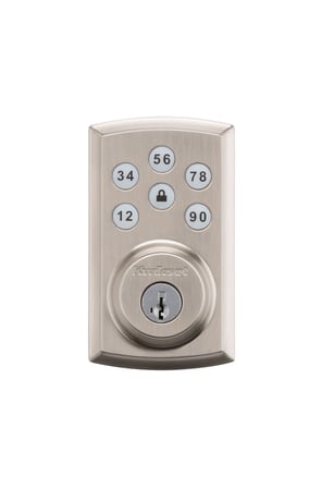
Product Picture


33 - SKU number, 1st 4 bytes
This configuration parameter provides the first 4 bytes of the SKU number that has been programmed into the lock.Size: 4 bytes
Default: 0
Minimum: 0
Maximum: 0
Possible values
| From | To | Desription |
|---|---|---|
| 32 | 126 | All printable characters |
34 - SKU number, last 4 bytes
This configuration parameter provides the second and last 4 bytes of the SKU number that has been programmed into the lock.Size: 4 bytes
Default: 0
Minimum: 0
Maximum: 0
Possible values
| From | To | Desription |
|---|---|---|
| 32 | 126 | All printable characters |
35 - Interior Status LED control
The configuration parameter 35 is a one byte field that will allow the user to get / set the value for the Interior Status LED control. The value of 0 means that the setting is disabled; whereas the value of 1 means that the setting is enabled. Sending a set command with the default field set to 1 will cause the control to revert back to its factory default setting.Size: 1 byte
Default: 1
Minimum: 0
Maximum: 0
Possible values
| From | To | Desription |
|---|---|---|
| 0 | 0 | disable status LED |
| 1 | 1 | enable status LED |
36 - Auto-lock Feature Control
The configuration parameter 36 uses 2 bytes that will allow the user to get / set the value for the Auto Lock feature and timing for that feature. The first byte will be the enable/disable byte. The value of 0 means that the setting is disabled; whereas the value of 1 means that the setting is enabled. The next two bytes will be the timing for the Auto Lock feature and should contain the number of seconds before the Auto Lock will occur. The valid values are: 0 (default – 30 seconds), 30, 60, 90, 120, 180. For example, setting the auto lock feature for 60 seconds, the two timing bytes should be: 0x003C. Sending a set command with the default field set to 1 will cause the control to revert back to its factory default settings.Size: 2 bytes
Default: 30
Minimum: 0
Maximum: 0
Possible values
| From | To | Desription |
|---|---|---|
| 0 | 0 | Byte 1: disable autolock |
| 1 | 1 | Byte 1: enable autolock |
| 30 | 30 | Byte 2: 30 second autolock |
| 60 | 60 | Byte 2: 60 second autolock |
| 90 | 90 | Byte 2: 90 second autolock |
| 120 | 120 | Byte 2: 120 second autolock |
| 180 | 180 | Byte 2: 180 second autolock |
37 - Audio Feature Control
The configuration parameter 37 is a one byte field that will allow the user to get / set the value for the Audio feature. The value of 0 means that the setting is disabled; whereas the value of 1 means that the setting is enabled. Sending a set command with the default field set to 1 will cause the control to revert back to its factory default setting.Size: 1 byte
Default: 1
Minimum: 0
Maximum: 0
Possible values
| From | To | Desription |
|---|---|---|
| 0 | 0 | disable audio feature |
| 1 | 1 | enable audio feature |
40 - Reset to Default
This configuration parameter allows the smart home controller to force a factory reset of the lock. After receiving this request, the lock will send a Device Reset Locally message back to the lifeline controller. The only possible value for this parameter is 1.Size: 1 byte
Default: 0
Minimum: 0
Maximum: 0
Possible values
| From | To | Desription |
|---|---|---|
| 0 | 0 | No Action |
| 1 | 1 | Force Factory Reset |
47 - Motor Load Test
The configuration parameter 47 uses 1 byte that will allow the user to get / set the value to enable or disable the motor load alarm. Setting this byte to 0 will disable the alarm, whereas setting this byte to 1 will enable the alarm. If a motor load alarm has been activated and the alarm has been enabled, the alarm will be sent via the Power Management group in the Notification Command Class as a Load Error (0x09).Size: 1 byte
Default: 0
Minimum: 0
Maximum: 0
Possible values
| From | To | Desription |
|---|---|---|
| 0 | 0 | do not run test |
| 1 | 1 | enable test to run |
Initiate the process to add the lock to your system at your smart home controller. When prompted by your smart home system to add the lock, press button “A” on the lock interior one time. The red LED will illuminate when the lock enters Add Mode. Please allow time for the controller to add the lock to your system.
Follow your smart home system’s instructions to remove the lock from the network. When prompted by the system, press button A” on the lock interior once. The red LED will illuminate when the lock enters Remove mode.
Even though the lock is sleeping, all buttons are active and can be used to initiate any lock activity. For the RF side, it will wake up every 1 second to check if there are any requests from your smart home controller.
A factory reset will delete all user codes associated with the lock and will remove itself from your smart home system. Please only perform a factory reset when the primary controller is missing or inoperable. To perform a factory reset, please perform the following: 1. Remove the battery pack 2. Press and HOLD the Program button while reinserting the battery pack. 3. Keep holding the button for 30 seconds until the lock beeps and the status LED flashes red. 4. Press the Program button once more. The status LED will flash green and red several times. 5. After a few seconds, the lock will initiate the door handing process.
| Type | Value(s) |
|---|