QUBINO
Qubino Flush Dimmer 0-10V
ZMNHVD1
Light Dimmer Switch
HW: 1 FW: 2.03:02.03
ZM5202
6.51.08
0x0159 (345)
0x0001 (1)
0x0053 (83)
ZC10-17025424
2017-02-08 01:27:08.89252
N/A
Enhanced 232 Slave
Always On Slave
The Qubino Flush Dimmer 0-10V is ideal for remotely dimming LED lights with low voltage ballast.
The Qubino Flush Dimmer 0-10V is a universal dimmer with a standard 0-10V output and a multi-function input, which may be a push button or switch, a potentiometer or a 0-10V signal. It also measures power consumption and supports the connection of a digital temperature sensor.
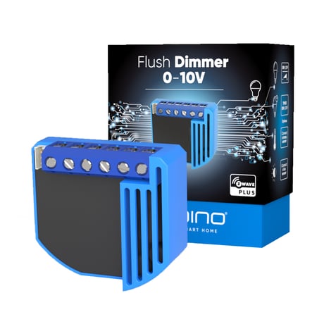
Product Picture


1 - Input 1 switch type
By this parameter the user can set input based on device type (switch, potentiometer, 0-10V sensor,..). NOTE: After parameter change to value 3, 4 or 5 first exclude module (without setting parameters to default value) then wait at least 30s and then re include the module!Size: 1 byte
Default: 0
Minimum: 0
Maximum: 0
Possible values
| From | To | Desription |
|---|---|---|
| 0 | 0 | Default value - Mono- stable switch type (push button) – button quick press turns between previous set dimmer value and zero) |
| 1 | 1 | Bi-stable switch type |
| 2 | 2 | Potentiometer (Flush Dimmer 0-10V is using set value the last received from potentiometer or from z-wave controller) |
| 3 | 3 | 0-10V Temperature sensor (regulated output) |
| 4 | 4 | 0-10V Illumination sensor (regulated output) |
| 5 | 5 | 0-10V General purpose sensor (regulated output) |
10 - Activate / deactivate functions ALL ON / ALL OFF
Flush Dimmer 0-10V module responds to commands ALL ON / ALL OFF that may be sent by the main controller or by other controller belonging to the system.Size: 2 bytes
Default: 255
Minimum: 0
Maximum: 0
Possible values
| From | To | Desription |
|---|---|---|
| 255 | 255 | Default value - ALL ON active, ALL OFF active |
| 0 | 0 | ALL ON is not active, ALL OFF is not active |
| 1 | 1 | ALL ON is not active, ALL OFF active |
| 2 | 2 | ALL ON active, ALL OFF is not active |
11 - Automatic turning off output after set time
Turns off the output after set time.Size: 2 bytes
Default: 0
Minimum: 0
Maximum: 0
Possible values
| From | To | Desription |
|---|---|---|
| 0 | 0 | Default value - Auto OFF disabled |
| 1 | 32536 | = 1second - 32536 seconds Auto OFF enabled with define time, step is 1 second |
12 - Automatic turning on output after set time
Turns on the output after set time.Size: 2 bytes
Default: 0
Minimum: 0
Maximum: 0
Possible values
| From | To | Desription |
|---|---|---|
| 0 | 0 | Default value - Auto ON disabled |
| 1 | 32535 | = 1second - 32535 seconds Auto ON enabled with define time, step is 1 second |
21 - Enable/Disable Double click function
If Double click function is enabled, a fast double click on the push button will set dimming power at maximum dimming value. Valid only if input is set as mono-stable (push button).Size: 1 byte
Default: 0
Minimum: 0
Maximum: 0
Possible values
| From | To | Desription |
|---|---|---|
| 0 | 0 | Default value - Double click disabled |
| 1 | 1 | Double click enabled |
30 - Saving the state of the device after a power failure
Based on the parameter settings the stores/does not store the last value of the output after power failure.Size: 1 byte
Default: 0
Minimum: 0
Maximum: 0
Possible values
| From | To | Desription |
|---|---|---|
| 0 | 0 | Default value - Flush Dimmer 0-10V module saves its state before power failure (it returns to the last position saved before a power failure) |
| 1 | 1 | Flush Dimmer 0-10V module does not save the state after a power failure, it returns to "off" position |
52 - Auto or manual selection
This parameter is influencing on the software only when the value of parameter number 1 is set to value 3, 4 or 5. In manual mode regulation (how the input influence on output) is disabled.Size: 1 byte
Default: 0
Minimum: 0
Maximum: 0
Possible values
| From | To | Desription |
|---|---|---|
| 0 | 0 | Default value - Manual |
| 1 | 1 | Auto |
53 - PID value inside deadband
NOTE: When ZERO PID inside deadband is forced to zero. LASTVALUE means that PID remains on same level as was before entering into deadband.Size: 1 byte
Default: 0
Minimum: 0
Maximum: 0
Possible values
| From | To | Desription |
|---|---|---|
| 0 | 0 | Default value - PID value equal ZERO |
| 1 | 1 | PID value set to LAST VALUE |
54 - PID deadband
NOTE: This parameter defines the zone where PID is not active. If the temperature difference between actual and setpoint is bigger than PID deadband, then the PID will start to regulate the system, otherwise the PID is zero or fixed.Size: 1 byte
Default: 1
Minimum: 0
Maximum: 0
Possible values
| From | To | Desription |
|---|---|---|
| 1 | 1 | Default value 1 (1%) |
| 0 | 100 | 0 - 100%, step is 1% |
55 - Integral sampling time
Parameter defines the time between samples. On each sample the controller capture difference between SP-act.Size: 1 byte
Default: 5
Minimum: 0
Maximum: 0
Possible values
| From | To | Desription |
|---|---|---|
| 5 | 5 | Default value 5 (5s) |
| 0 | 127 | = 0s to 127s, step is 1s |
56 - P parameter
The error is multiplied by a negative (for reverse action) proportional constant P, and added to the current output. P represents the band over which a controller's output is proportional to the error of the system. E.g. for a heater, a controller with a proportional band of 10 deg C and a setpoint of 100 deg C would have an output of 100% up to 90 deg C, 50% at 95 Deg C and 10% at 99 deg C. If the temperature overshoots the setpoint value, the heating power would be cut back further. Proportional only control can provide a stable process temperature but there will always be an error between the required setpoint and the actual process temperature.Size: 2 bytes
Default: 100
Minimum: 0
Maximum: 0
Possible values
| From | To | Desription |
|---|---|---|
| 100 | 100 | Default value |
| 0 | 1000 | P value, step is 1 |
57 - I parameter
The error is integrated (averaged) over a period of time, and then multiplied by a constant I, and added to the current control output. I represents the steady state error of the system and will remove setpoint / measured value errors. For many applications Proportional + Integral control will be satisfactory with good stability and at the desired setpoint.Size: 2 bytes
Default: 1
Minimum: 0
Maximum: 0
Possible values
| From | To | Desription |
|---|---|---|
| 1 | 1 | Default value |
| 0 | 1000 | I value, step is 1 |
58 - D parameter
The rate of change of the error is calculated with respect to time, multiplied by another constant D, and added to the output. The derivative term is used to determine a controller's response to a change or disturbance of the process temperature (e.g. opening an oven door). The larger the derivative term, the more rapidly the controller will respond to changes in the process value.Size: 2 bytes
Default: 1
Minimum: 0
Maximum: 0
Possible values
| From | To | Desription |
|---|---|---|
| 1 | 1 | Default value |
| 0 | 1000 | D value, step is 1 |
60 - Minimum dimming value
NOTE: The minimum level may not be higher than the maximum level! 1% min. dimming value is defined by Z-Wave multilevel device class. When the switch type is selected as Bi-stable, it is not possible to dim the value between min and max. If Switch_multilevel_set is set to the value “0”, the output is turned OFF. If Switch_multilevel_set is set to the value “1”, the output is set to the minimum diming value.Size: 1 byte
Default: 1
Minimum: 0
Maximum: 0
Possible values
| From | To | Desription |
|---|---|---|
| 1 | 1 | Default value = 1% (minimum dimming value) |
| 1 | 98 | = 1% - 98%, step is 1%. Minimum dimming values is set by entered value |
61 - Maximum dimming value
NOTE: The maximum level may not be lower than the minimum level! 99% max. dimming value is defined by Z-Wave multilevel device class. When the switch type is selected as Bi-stable, it is not possible to dim the value between min and max.Size: 1 byte
Default: 99
Minimum: 0
Maximum: 0
Possible values
| From | To | Desription |
|---|---|---|
| 99 | 99 | Default value = 99% (Maximum dimming value) |
| 2 | 99 | = 2% - 99%, step is 1%. Maximum dimming values is set by entered value. |
65 - Dimming time (soft on/off)
Set value means time of moving the Flush Dimmer 0-10V between min. and max. dimming values by short press of push button I1 or controlled through UI (BasicSet).Size: 2 bytes
Default: 100
Minimum: 0
Maximum: 0
Possible values
| From | To | Desription |
|---|---|---|
| 100 | 100 | Default value 100 = 1s |
| 50 | 255 | = 500 mseconds - 2550 mseconds (2,55s), step is 10 mseconds |
66 - Dimming time when key pressed
Time of moving the Flush Dimmer 0-10V between min. and max dimming values by continues hold of push button I1 or associated device.Size: 2 bytes
Default: 3
Minimum: 0
Maximum: 0
Possible values
| From | To | Desription |
|---|---|---|
| 3 | 3 | Default value 3 = 3s |
| 1 | 255 | = 1 second - 255 seconds |
67 - Ignore start level
This parameter is used with association group 3. A receiving device SHOULD respect the start level if the Ignore Start Level bit is 0. A receiving device MUST ignore the start level if the Ignore Start Level bit is 1.Size: 1 byte
Default: 0
Minimum: 0
Maximum: 0
Possible values
| From | To | Desription |
|---|---|---|
| 0 | 0 | Default value - Respect start level |
| 1 | 1 | Ignore start level |
68 - Dimming duration
This parameter is used with association group 3. The Duration field MUST specify the time that the transition should take from the current value to the new target value. A supporting device SHOULD respect the specified Duration value.Size: 1 byte
Default: 0
Minimum: 0
Maximum: 0
Possible values
| From | To | Desription |
|---|---|---|
| 0 | 0 | Default value - dimming duration according to parameter 66 |
| 1 | 127 | From 1 to 127 seconds |
110 - Temperature sensor offset settings
Set value is added or subtracted to actual measured value by sensor.Size: 2 bytes
Default: 32536
Minimum: 0
Maximum: 0
Possible values
| From | To | Desription |
|---|---|---|
| 32536 | 32536 | Default value - offset is 0.0 degrees celsius |
| 1 | 100 | Value from 0.1 degrees celsius to 10.0 degrees celsius is added to actual measured temperature |
| 1001 | 1100 | Value from -0.1 degrees celsius to -10.0 degrees celsius is subtracted to actual measured temperature |
120 - Digital temperature sensor reporting
Digital temperature sensor reporting If digital temperature sensor is connected, module reports measured temperature on temperature change defined by this parameter. Available configuration parameters (data type is 1 Byte DEC): • default value 5 = 0,5°C change • 0 - Reporting disabled • 1 - 127 = 0,1°C - 12,7°C, step is 0,1°CSize: 1 byte
Default: 5
Minimum: 0
Maximum: 0
Possible values
| From | To | Desription |
|---|---|---|
| 5 | 5 | Default value = 0,5 degrees celsius change |
| 0 | 0 | Reporting disabled |
| 1 | 127 | 0,1 degrees celsius - 12,7 degrees celsius, step is 0,1 degrees celsius |
140 - Input I1 Sensor reporting
Input I1 Sensor reporting If analogue sensor is connected, module reports measured value on change defined by this parameter.Size: 2 bytes
Default: 5
Minimum: 0
Maximum: 0
Possible values
| From | To | Desription |
|---|---|---|
| 5 | 5 | Default value = 0,5 change |
| 0 | 0 | Reporting disabled |
| 1 | 10000 | = 0,1 - 1000 step is 0,1 |
141 - Input I1 0-10V reporting threshold
Parameter is associated with Association group No. 2. Below this value, the Association No. 2 will report Basic Set 0xFF and above this value will report Basic Set 0xFF. Basic Set is reported only, when the input value changes for more than 10% (1V).Size: 1 byte
Default: 5
Minimum: 0
Maximum: 0
Possible values
| From | To | Desription |
|---|---|---|
| 5 | 5 | Default value = 5 (0,5V) |
| 1 | 100 | 0,1 - 10V |
143 - Minimum sensor range value
Value that must correspond to minimum sensor range value. Valid only if parameter 1 is set to values 3, 4 or 5). Available configuration parameters (data type is 2 Byte DEC): • default value 0 = 0.0°C / 0Lux / 0.0%rh • 0 - 10000 – value from 0 to 1000 (resolution 0,1) • 10001 – 20000 – value from -0,1 to -1000 (resolution 0,1) NOTE: Minimum value must not be higher than maximum value!Size: 2 bytes
Default: 0
Minimum: 0
Maximum: 0
Possible values
| From | To | Desription |
|---|---|---|
| 0 | 0 | Default value 0 = 0.0 degrees celsius / 0Lux / 0.0%rh |
| 0 | 10000 | Value from 0 to 1000 (resolution 0,1) |
| 10001 | 20000 | Value from -0,1 to -1000 (resolution 0,1)alue from -0,1 to -1000 (resolution 0,1) |
144 - Maximum sensor range value
Value that must correspond to maximum sensor range value. Valid only if parameter 1 is set to values 3, 4 or 5). NOTE: Maximum value must not be lower than minimum value!Size: 2 bytes
Default: 1000
Minimum: 0
Maximum: 0
Possible values
| From | To | Desription |
|---|---|---|
| 1000 | 1000 | Default value - 1000 = 100.0 degrees celsius / 100Lux / 100%rh |
| 0 | 10000 | Value from 0 to 1000 (resolution 0,1) |
| 10001 | 20000 | Value from -0,1 to -1000 (resolution 0,1) |
250 - Unsecure / Secure Inclusion
A Flush dimmer supports secure and unsecure inclusion. Even if the controller does not support security command classes, a dimmer could be included as unsecure and keep all the functionality.Size: 1 byte
Default: 0
Minimum: 0
Maximum: 0
Possible values
| From | To | Desription |
|---|---|---|
| 0 | 0 | Default value - Unsecure Inclusion |
| 1 | 1 | Secure Inclusion |
• Connect module to power supply (with temperature sensor connected - if purchased), • enable add/remove mode on main controller • auto-inclusion (works for about 5 seconds after connected to power supply) or • press service button S for more than 2 second or • press push button I1 three times within 3s (3 times change switch state within 3 seconds). NOTE1: For auto-inclusion procedure, first set main controller into inclusion mode and then connect module to power supply. NOTE2: When connecting temperature sensor to module that has already been included, you have to exclude module first. Switch off power supply, connect the sensor and re-include the module.
• Connect module to power supply • bring module within maximum 1 meter (3 feet) of the main controller, • enable add/remove mode on main controller, • press push button I1 five times within 3s (5 times change switch state within 3 seconds) in the first 60 seconds after the module is connected to the power supply or • press service button S (only applicable for 24 V SELV supply voltage) for more than 6 second. By this function all parameters of the module are set to default values and own ID is deleted. If push button I1 is pressed three times within 3s (or service button S is pressed more than 2 and less than 6 seconds) module is excluded, but configuration parameters are not set to default values. NOTE 1: If the module is included with parameter 1 value 3, 4 or 5 and module reset is done, wait at least 30s before next inclusion. NOTE 2: Please use this procedure only when the network primary controller is missing or otherwise inoperable.
• Press push button I1 five times within 3s (5 times change switch state within 3 seconds) in the first 60 seconds after the module is connected to the power supply or • press service button S (only applicable for 24 V SELV supply voltage) for more than 6 second. Please use this procedure only when the network primary controller is missing or otherwise inoperable.
| Type | Value(s) |
|---|
| Sensor type |
|---|
| Air Temperature |
| Water Temperature |