COMAP
In-Wall On/Off Switch Module
LIZY0005
On/Off Power Switch
HW: 2 FW: 1.02:00.01
SD3502
6.51.02
0x0329 (809)
0x0004 (4)
0x0008 (8)
ZC10-17025432
2017-02-10 18:56:55.426303
N/A
Enhanced 232 Slave
Always On Slave
The LIZY0005 is an in-wall on/off switch module.
The In-Wall On/Off Module is a Z-Wave enabled device which is fully compatible with any Z-Wave enabled network. Z-Wave enabled devices displaying the Z-Wave logo can also be used with it regardless of the manufacturer, and ours can also be used in other manufacturer’s Z-Wave enabled networks. Inclusion of this unit on other manufacturer’s Wireless Controller menu allows remote operation of the unit and the connected load. Z-Wave node in the system also acts as a repeater, so the RF signal can reach its intended receiver by routing around obstacles and radio dead spots. The In-Wall On/Off Module is designed to control the on/off status of lighting and appliances load in your house. Two sets of dry contacts provide more wiring applications. For security, the unit can detect overheating and will turn off relay automatically to avoid damage. At 230V voltage, this module can support up to 2500W resistive, 1200W incandescent, 700W motor, or 320W (40W*8) fluorescent load.
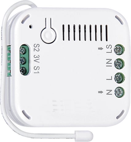
Product Picture


1 - Basic Set Command value
The Basic Set value.Size: 2 bytes
Default: 255
Minimum: 0
Maximum: 0
Possible values
| From | To | Desription |
|---|---|---|
| 0 | 99 | Dimmer Value |
| 255 | 255 | switch on |
2 - The delaying time to report to Group 1:
delay for while second to sendSize: 1 byte
Default: 3
Minimum: 0
Maximum: 0
Possible values
| From | To | Desription |
|---|---|---|
| 3 | 25 | unit is second |
3 - Remember the last status
to setup remember the on/off last status if power applied 1: remember 0: do not rememberSize: 1 byte
Default: 1
Minimum: 0
Maximum: 0
Possible values
| From | To | Desription |
|---|---|---|
| 0 | 1 | remember or not |
4 - Switch 1 switching type
setup the Switch Contact switch mode 0: Single Pole Double Throw 1: Toggle switchSize: 1 byte
Default: 0
Minimum: 0
Maximum: 0
Possible values
| From | To | Desription |
|---|---|---|
| 0 | 1 | mode 1 or mode 2 |
1. Put the Z-Wave Controller into inclusion mode. 2. Press the link key three times within 1.5 seconds to put the unit into inclusion mode.
1. Put the Z-Wave Controller into exclusion mode. 2. Press the link key three times within 1.5 seconds to put the unit into exclusion mode.
(This procedure should only be used when the primary controller is no longer operational.) 1. Press the link key three times within 1.5 seconds to put the unit into exclusion mode. 2. Within 1 second of step 1, press link key again and hold until LED is off (about 5 sec.). 3. Node ID is excluded, and the unit is returned to the factory default state.
| Type | Value(s) |
|---|
| Group | Type |
|---|---|
| System | (Refer to parameters): State idle |