QUBINO
Flush Shutter
ZMNHCD1
Window Covering - Pos/End Aware
HW: 1 FW: 6.04:06.05
ZM5202
6.51.09
0x0159 (345)
0x0003 (3)
0x0052 (82)
ZC10-17045565
2017-04-26 23:41:17.916393
N/A
Enhanced 232 Slave
Always On Slave
The Qubino Flush Shutter is the world's smallest Z-Wave module able to control the motors of blinds, rollers, shades, venetian blinds, etc.
This Z-Wave module is used to control the motor of blinds, rollers, shades, venetian blinds, etc … The module can be controlled either through a Z-Wave network or through the wall switch. Precise positioning is supported for motors equipped with mechanical or electronic end switches. The module is designed to be mounted inside a “flush mounting box”, hidden behind a traditional wall switch. Module measures power consumption of motor and support connection of digital temperature sensor. It is designed to act as repeater in order to improve range and stability of Z-wave network.
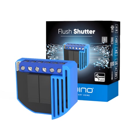
Product Picture


10 - Activate/deactivate functions ALL ON / ALL OFF
Flush Shutter responds to commands ALL ON / ALL OFF that may be sent by the main controller or by other controllers belonging to the system.Size: 2 bytes
Default: 255
Minimum: 0
Maximum: 0
Possible values
| From | To | Desription |
|---|---|---|
| 255 | 255 | ALL ON active, ALL OFF active |
| 0 | 0 | ALL ON is not active ALL OFF is not activ |
| 1 | 1 | ALL ON is not active ALL OFF active |
| 2 | 2 | ALL ON active ALL OFF is not active |
40 - Power reporting in Watts on power change for Q1 or Q2
Set value means percentage, set value from 0 – 100 = 0% - 100%.Size: 1 byte
Default: 10
Minimum: 0
Maximum: 0
Possible values
| From | To | Desription |
|---|---|---|
| 0 | 0 | Reporting disabled |
| 1 | 100 | = 1% - 100% Reporting enabled. Power report is send (push) only when actual power (in Watts) in real time changes for more than set percentage comparing to previous actual power in Watts, step is 1%. NOTE: if power changed is less than 1W, the report is not send (pushed), independent of percentage set. |
42 - Power reporting in Watts by time interval for Q1 or Q2
Set value means time interval (0 – 32767) in seconds, when power report is send.Size: 2 bytes
Default: 0
Minimum: 0
Maximum: 0
Possible values
| From | To | Desription |
|---|---|---|
| 0 | 0 | Reporting disabled |
| 1 | 32767 | = 1 second - 32767 seconds. Reporting enabled, power report is send with time interval set by entered value |
71 - Operating modes
This parameter defines selection between two available operating modes. NOTE1: After parameter change, first exclude module (without setting parameters to default value) then wait at least 30s and then re include the module!Size: 1 byte
Default: 0
Minimum: 0
Maximum: 0
Possible values
| From | To | Desription |
|---|---|---|
| 0 | 0 | Shutter mode |
| 1 | 1 | Venetian mode (up/down and slate rotation) |
72 - Slats tilting full turn time
This parameter defines the time necessary for slats to make full turn (180 degrees).Size: 2 bytes
Default: 150
Minimum: 0
Maximum: 0
Possible values
| From | To | Desription |
|---|---|---|
| 150 | 150 | = 1,5 seconds |
| 0 | 0 | Tilting time disabled |
| 2 | 32767 | = 0,01seconds - 327,67 seconds |
73 - Slats position
This parameter defines slats position after up/down movement through Z-wave or push-buttons. • default value 1 • 0 - Slats return to previously set position only in case of Z-wave control (not valid for limit switch positions). • 1 - Slats return to previously set position in case of Z-wave control, push-button operation or when the lower limit switch is reached.Size: 1 byte
Default: 1
Minimum: 0
Maximum: 0
Possible values
| From | To | Desription |
|---|---|---|
| 1 | 1 | Slats return to previously set position in case of Z-wave control, push-button operation or when the lower limit switch is reached |
| 0 | 0 | Slats return to previously set position only in case of Z-wave control (not valid for limit switch positions) |
74 - Motor moving up/down time
This parameter defines Shutter motor moving time of complete opening or complete closing. NOTE: Important is that the reference position to manually set moving time is always Shutter lower position! Set parameter 74 to 0 and move the Shutter (using up/down push buttons or main controller UI) to the lowest desired position. On this Shutter position, set parameter 74 to time for complete opening or complete closing. At this point Shutter can be moved up (open) for set time, but can't be moved down because this position is already set as lower Shutter position. To change Shutter lower position below already set (manual recalibration), parameter 74 must be set to 0 and repeat the procedure described above. In case Shutter has limit switches, but anyhow you would like to limit opening/closing position by time, you can still do it. In case you put time that is longer that opening/closing real time limited by limit switches, Shutter will stop at limit switch, but the module relay will switch off after define time, not by Shutter limit switch. Take in consideration that in this condition, the positioning with slider through UI will not show correct Shutter position.Size: 2 bytes
Default: 0
Minimum: 0
Maximum: 0
Possible values
| From | To | Desription |
|---|---|---|
| 0 | 0 | Moving time disabled (working with limit switches) |
| 1 | 32767 | = 0,1 seconds - 3276,7 seconds. After that time motor is stopped (relay goes to off state) |
76 - Motor operation detection
Power threshold to be interpreted when motor reach the limit switch.Size: 1 byte
Default: 30
Minimum: 0
Maximum: 0
Possible values
| From | To | Desription |
|---|---|---|
| 0 | 127 | = 1-127 W. The value 0 means reaching a limit switch will not be detected |
78 - Forced Shutter calibration
By modifying the parameters setting from 0 to 1 a Shutter enters the calibration mode.Size: 1 byte
Default: 0
Minimum: 0
Maximum: 0
Possible values
| From | To | Desription |
|---|---|---|
| 1 | 1 | Start calibration process (when calibration process is finished, completing full cycle - up, down and up, set the parameter 78 (Forced Shutter calibration) value back to 0 |
| 0 | 0 |
85 - – Power consumption max delay time
This parameter defines the max time before motor power consumption is read after one of the relays is switched ON. If there is no power consumption during this max time (motor not connected, damaged or requires higher time to start, motor in end position) the relay will switch OFF. Time is defined by entering it manually.Size: 1 byte
Default: 30
Minimum: 0
Maximum: 0
Possible values
| From | To | Desription |
|---|---|---|
| 30 | 30 | = 3s |
| 0 | 0 | = time is set automatically |
| 3 | 50 | = 0,3seconds - 5seconds (100ms resolution) |
90 - Time delay for next motor movement
This parameter defines the minimum time delay between next motor movement (minimum time between switching motor off and on again).Size: 1 byte
Default: 5
Minimum: 0
Maximum: 0
Possible values
| From | To | Desription |
|---|---|---|
| 5 | 5 | = 500ms |
| 1 | 30 | = 0,1seconds - 3seconds (100ms resolution) |
110 - Temperature sensor offset settings
Set value is added or subtracted to actual measured value by sensor.Size: 2 bytes
Default: 32536
Minimum: 0
Maximum: 0
Possible values
| From | To | Desription |
|---|---|---|
| 32536 | 32536 | Offset is 0.0 Degrees Celsius |
| 1 | 100 | Value from 0.1 Degrees Celsius to 10.0 Degrees Celsius is added to actual measured temperature |
| 1001 | 1100 | Value from -0.1 Degrees Celsius to -10.0 Degrees Celsius is subtracted to actual measured temperature |
120 - Temperature sensor reporting
If digital temperature sensor is connected, module reports measured temperature on temperature change defined by this parameter. Available configuration parameters (data type is 1 Byte DEC): • default value 5 = 0,5°C • 0 - Reporting disabled • 1-127 = 0,1°C - 12,7°C, step is 0,1°CSize: 1 byte
Default: 5
Minimum: 0
Maximum: 0
Possible values
| From | To | Desription |
|---|---|---|
| 5 | 5 | = 0,5 Degrees Celsius |
| 0 | 0 | Reporting disabled |
| 1 | 127 | = 0,1 Degrees Celsius - 12,7 Degees Celsius; step is 0,1 Degrees Celsius |
250 - Unsecure / Secure Inclusion
Flush Shutter supports secure and unsecure inclusion. Even if the controller does not support security command classes, a dimmer could be included as unsecure and keep all the functionality.Size: 1 byte
Default: 0
Minimum: 0
Maximum: 0
Possible values
| From | To | Desription |
|---|---|---|
| 0 | 0 | Unsecure Inclusion |
| 1 | 1 | Secure Inclusion |
• Connect module to power supply (with temperature sensor connected - if purchased), • auto-inclusion (works for about 5 seconds after connected to power supply) or • press push button I1 three times within 3s (3 times change switch state within 3 seconds) or • press service button S (only applicable for 24 V SELV supply voltage) for more than 2 second. NOTE1: For auto-inclusion procedure, first set main controller into inclusion mode and then connect module to power supply. NOTE2: When connecting temperature sensor to module that has already been included, you have to exclude module first. Switch off power supply, connect the sensor and re-include the module.
• Connect module to power supply • bring module within maximum 1 meter (3 feet) of the main controller, • enable add/remove mode on main controller, • press push button I1 five times within 3s (5 times change switch state within 3 seconds) in the first 60 seconds after the module is connected to the power supply or • press service button S (only applicable for 24 V SELV supply voltage) for more than 6 second. By this function all parameters of the module are set to default values and own ID is deleted. If push button I1 is pressed three times within 3s (or service button S is pressed more than 2 and less than 6 seconds) module is excluded, but configuration parameters are not set to default values. NOTE: Please use this procedure only when the network primary controller is missing or otherwise inoperable. NOTE: If the module is included with parameters 71 with value different to default and module reset is done, wait at least 30s before next inclusion
• press push button I1 five times within 3s (5 times change switch state within 3 seconds) in the first 60 seconds after the module is connected to the power supply or • press service button S (only applicable for 24 V SELV supply voltage) for more than 6 second. NOTE: Please use this procedure only when the network primary controller is missing or otherwise inoperable.
| Type | Value(s) |
|---|
| Group | Type |
|---|---|
| Power Management | (Refer to parameters): State idle |
| Sensor type |
|---|
| Air Temperature |
| Water Temperature |
| Meter type |
|---|
| Electric Meter Consumption |