Zipato
Micro Module Switch Double w.meter
ph-pan04.eu
On/Off Power Switch
HW: 1 FW: 1.08
SD3502
6.51.02
0x0131 (305)
0x0001 (1)
0x0012 (18)
ZC10-17065647
2017-06-07 22:40:15.31687
N/A
Enhanced 232 Slave
Always On Slave
Micromodule Switch Double is a transceiver which is a Z-Wave Plus enabled device and is fully compatible with any Z-Wave enabled etwork.
This product can be operated in any Z-Wave network with other Z-Wave certified devices from other manufacturers. All non-battery operated nodes within the network will act as repeaters regardless of vendor to increase reliability of the network. Micromodule Switch Double is a transceiver which is a Z-Wave Plus enabled device and is fully compatible with any Z-Wave enabled network. Mini size design allow the module to be easily hidden into the wall box which is good for the house decoration. There are many kinds of application for using the module to switch AC power ON and OFF, one of which is the light control. The new smart relay calibration technology can reduce the inrush current caused by the load and let the module work perfectly with many kinds of light like incandescent, fluorescent and LED light. This Micromodule is able to detect Instant power wattage and overload wattage (current 7.5A) of connected light or appliances. When detecting overload state, the switch will be disabled and its ON/OFF button will be locked during which LED will flash repeatedly. Unplugging and reconnecting the Module will reset its overload condition to normal status.
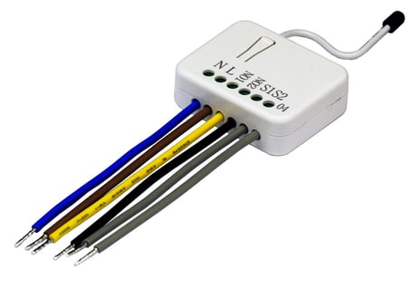
Product Picture


1 - Watt Meter Report Period
If the setting is configured for 1hour (set value =720), Micromodule will report its instant power consumption every 1 hour to the node of correspond Group. The maximum interval to report its instant power consumption is 45 hours (5s*32767/3600=45hr).Size: 2 bytes
Default: 720
Minimum: 0
Maximum: 0
Possible values
| From | To | Desription |
|---|---|---|
| 1 | 32767 | 5*720s=3600s=1 hour |
2 - KWH Meter Report Period
If the setting is configured for 1hour (set value =6), Micromodule will report its Accumulated Power Consumption (KW/h) every 1 hour to the node of correspond Group. The maximum interval to report its Accumulated Power Consumption (KW/h) is 227.55 days (10min*32767/1440=227.55 days).Size: 2 bytes
Default: 6
Minimum: 0
Maximum: 0
Possible values
| From | To | Desription |
|---|---|---|
| 1 | 32767 | 6*10min= 1 hour |
3 - Slected End Point
If Micromodule is not using Multi_Channel command class to access the relay of Switch, you may configure the select value to react the Basic Command Class, Binary Switch Command Class or Meter Command Class V3. 1.SELECTED RELAY1: Only relay1 can be controlled and report. 2.SELECTED RELAY2: Only relay2 can be controlled and report. 3.SELECTED RELAY1 AND RELAY2: DEFAULT SELECT IS 3 Both relay1 and relay2 can be controlled and report.Size: 1 byte
Default: 1
Minimum: 0
Maximum: 0
Possible values
| From | To | Desription |
|---|---|---|
| 1 | 1 | 1: Relay1 |
| 2 | 2 | 2: Relay2 |
| 3 | 3 | 3: Relay1 & Relay2 |
4 - Edge or Pulse mode or Edge-Toggle mode
Manual switch S1 and S2 can set to Edge mode or Pulse mode or Edge-Toggle mode, default value is Edge mode. 1.EDGE MODE : This mode is suitable for the bi stable wall switch that has indicator point on the Micromodule, and the same position correspond to same state of relay1 and relay2. if the Switch’s relay changes the state because of receiving Z-Wave RF command, it may need two switchings (switch on to off or switch off to on) to let relay back to the corresponding state. 2.PULSE MODE : This mode is suitable for the toggle type wall switch to swap the state of Relay1 or Relay2. 3. EDGE-TOGGLE MODE : This mode is suitable for the normal bi-stable switch, every state change of the wall switch will also swap the state of Relay1 or Relay2.Size: 1 byte
Default: 1
Minimum: 0
Maximum: 0
Possible values
| From | To | Desription |
|---|---|---|
| 1 | 1 | 1: Edge mode |
| 2 | 2 | 2: Pulse mode |
| 3 | 3 | 3: Edge-Toggle mode |
5 - Threshold of Current for Load Caution
This is a warning when the wattage of load over the preset threshold value, If the setting value is 750, when the load wattage of Relay1 or Relay2 over this value, Micromodule will send Watt Meter Report command to the node of correspond Group, the Range of the setting value is from 10 to 750, and the default value is 750.Size: 2 bytes
Default: 750
Minimum: 0
Maximum: 0
Possible values
| From | To | Desription |
|---|---|---|
| 10 | 750 | 750*0.01A = 7.5A |
6 - Threshold of KWH for Load Caution
This is a warning when the KWh of load exceeds preset threshold value, If the setting value is 1000, when the Accumulated Power Consumption of Relay1 or Relay2 exceeds this value, Micromodule will send KWh Meter Report command to the node of corresponding Group, the Range of the setting value is from 10 to 1000, and the default value is 750.Size: 2 bytes
Default: 10000
Minimum: 0
Maximum: 0
Possible values
| From | To | Desription |
|---|---|---|
| 1 | 10000 | 10000*1KWh = 10000KWh |
7 - Restore switch state mode
Whenever the AC power return from lost, Micromodule will restore the switch state which could be SWITCH OFF, LAST SWITCH STATE, SWITCH ON. The default setting is LAST SWITCH STATE.Size: 1 byte
Default: 1
Minimum: 0
Maximum: 0
Possible values
| From | To | Desription |
|---|---|---|
| 0 | 0 | 0: Switch off |
| 1 | 1 | 1: Last switch state |
| 2 | 2 | 2: Switch on |
8 - Auto off timer
Whenever Micromodule switches to on, the auto off timer begin to count down. After the timer decrease to zero, it will switch off automatically. However if Auto off timer is set as 0, the auto off function will be disabled. The default setting is 0.Size: 2 bytes
Default: 0
Minimum: 0
Maximum: 0
Possible values
| From | To | Desription |
|---|---|---|
| 0 | 0 | 0: Disable auto off function |
| 1 | 32767 | 1-0x7FFF: 1s - 32767s |
9 - RF Switch off command mode
Whenever a switch off command, BASIC_SET , BINARY_SWITCH_SET, SWITCH_ALL_OFF, is received, it could be interpreted as 4 kinds of commands. 1.SWITCH OFF : It switches to OFF state. The default setting is Switch Off. 2.IGNORE : The switch off command will be ignored. 3.SWITCH TOGGLE : It switches to the inverse of current state. 4.SWITCH ON : It switches to ON state.Size: 1 byte
Default: 0
Minimum: 0
Maximum: 0
Possible values
| From | To | Desription |
|---|---|---|
| 0 | 0 | 0: Switch off |
| 1 | 1 | 1: Ignore |
| 2 | 2 | 2: Switch toogle |
| 3 | 3 | 3:Switch on |
10 - Existence of Endpoint3
Multi-Channel Command is a good way to control relay1 and relay2 of Switch individually. The endpoint3 of Micromodule is related to both relay1 and relay2. In some condition it becomes redundant in Multi-Channel Command Class. When the Existence of Endpoint3 is set as 2, the endpoint3 will be disabled. The default value is 1. Endpoint1 and Endpoint2 are fixed, only Endpoint3 is dynamic.Size: 1 byte
Default: 1
Minimum: 0
Maximum: 0
Possible values
| From | To | Desription |
|---|---|---|
| 1 | 1 | 1: Endpoint exist |
| 2 | 2 | 2: No Endpoint3 |
Have Z-Wave Controller entered inclusion mode by following the instructions provided by the controller manufacturer. Pressing INCLUDE_BUTTON threetimes within 2 seconds will enter inclusion mode.
Have Z-Wave Controller entered exclusion mode by following the instructions provided by the controller manufacturer. Pressing INCLUDE_BUTTON three times within 2 seconds will enter exclusion mode. Node ID has been excluded.
Use this procedure only in the event that the network primary controller is lost or otherwise inoperable. Pressing INCLUDE_BUTTON three times within 2 seconds will enter inclusion mode. Within 1 second, press On/Off button again for 5 seconds until LED is off. IDs are excluded.
| Type | Value(s) |
|---|
| Meter type |
|---|
| Electric Meter Consumption |