Siterwell Technology
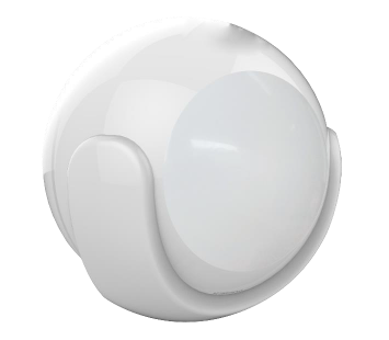
Siterwell Motion Sensor
STW-W3300WU
Notification Sensor
HW: 66 FW: 3.80
ZM5202
6.51.06
0x0266 (614)
0x0003 (3)
0x0300 (768)
ZC10-17085750
2017-08-25 21:33:15.913097
N/A
Routing Slave
Reporting Sleeping Slave
Yes
This product can be included and operated in any Z‐Wave network with other Z‐Wave certified devices from other manufacturers and/or other applications. All non‐battery operated nodes within the network will act as repeaters regardless of vendor to increase reliability of the network.
This product can be included and operated in any Z‐Wave network with other Z‐Wave certified devices from other manufacturers and/or other applications. All non‐battery operated nodes within the network will act as repeaters regardless of vendor to increase reliability of the network. In the Back casing, there is a button that is used to carry out include, exclude, wake up device or reset factory default settings. When power is first supplied, the LED will flash on and off alternately at one second intervals within 5 seconds if the detector has not been added a Z‐Wave network. Please get familiar with the terms below before starting the operations.


1 - Sensitivity Level Setting
This parameter defines the sensitivity of PIR detector, it is recommended to test the detector with movements from a farthest end of the coverage area at first time of use. If movements cannot be detected sensitively, simply adjust the sensitivity level with this parameter. This Parameter can be configured with the value of 8 through 255, where 8 means high sensitivity and 255 means lowest sensitivity.Size: 1 byte
Default: 12
Minimum: 0
Maximum: 0
Possible values
| From | To | Desription |
|---|---|---|
| 8 | 255 | unsigned |
2 - On/Off Duration Setting
This parameter can be determined how long the associated devices should stay ON status. For instance, this parameter is set to 30(second), the PIR detector will send a BASIC_SET Command to an associated device with value basic set level if PIR detector is triggered and the associated device will be turned on 30(second) before it is turned off. This Parameter value must be large than Parameter 6#. If user set this parameter to default by Configure CC, the parameter #6 will be set to default value.Size: 2 bytes
Default: 30
Minimum: 0
Maximum: 0
Possible values
| From | To | Desription |
|---|---|---|
| 5 | 600 | second . unsigned |
3 - Basic Set Level
Basic Set Command will be sent where contains a value when PIR detector is triggered, the receiver will take it for consideration; for instance, if a lamp module is received the Basic Set Command of which value is decisive as to how bright of dim level of lamp module shall be. This Parameter is used to some associated devices.Size: 1 byte
Default: 255
Minimum: 0
Maximum: 0
Possible values
| From | To | Desription |
|---|---|---|
| 0 | 0 | 0, 1 ~ 99 or 255 0 – OFF, Alarm cancelling or turning a device off 1 ~ 99 or 255 – ON (Binary Switch Device) Dim Level (Multilevel Switch Device) |
4 - Enabled/Disabled PIR Function
This parameter can be enabled or disabled the PIR detector detecting function.Size: 1 byte
Default: 255
Minimum: 0
Maximum: 0
Possible values
| From | To | Desription |
|---|---|---|
| 0 | 0 | – Disable PIR Detector Function. unsigned |
| 255 | 255 | – Enable PIR Detector Function. unsigned |
5 - Lux Level Set
This parameter can be set a lux level value which determines when the light sensor is activated. If the ambient illumination level falls below this value and a person moves across or within the detected area , PIR detector will send a Z‐Wave ON command(i.e. BASIC_SET (value = parameter 3) to an associated device and activate it.Size: 2 bytes
Default: 100
Minimum: 0
Maximum: 0
Possible values
| From | To | Desription |
|---|---|---|
| 0 | 1000 | Lux .unsigned |
6 - Re‐trigger Interval Setting.
This Parameter can be used to adjust the interval of being re‐triggered after the PIR detector has been triggered. This Parameter value must be less than Parameter 2#. If user set this parameter to default by Configure CC, the parameter #2 will be set to default value.Size: 1 byte
Default: 8
Minimum: 0
Maximum: 0
Possible values
| From | To | Desription |
|---|---|---|
| 1 | 8 | second .unsigned |
7 - Light Sensor Polling Interval
This Parameter can be set the light sensor measure ambient illumination level interval time. NOTE: This Value Must Be less than Wakeup Interval Time.Size: 2 bytes
Default: 180
Minimum: 0
Maximum: 0
Possible values
| From | To | Desription |
|---|---|---|
| 60 | 36000 | second .unsigned |
8 - Lux Level Enable
If this parameter is set to ‘1’, and when Lux level less than the value define by parameter #5, PIR detector will send a BASIC_SET command frame(i.e. BASIC_SET (value = parameter 3) to an associated device and activate it. If Lux Level greater than the value define by parameter #5, PIR detector will not send a BASIC_SET command frame.Size: 1 byte
Default: 0
Minimum: 0
Maximum: 0
Possible values
| From | To | Desription |
|---|---|---|
| 0 | 1 | unsigned |
9 - Lux Level Report
This parameter defines by how much Lux Level must change, in lux, to be reported to the main controller.Size: 2 bytes
Default: 100
Minimum: 0
Maximum: 0
Possible values
| From | To | Desription |
|---|---|---|
| 0 | 255 | Lux. unsigned |
10 - Led Blink Enable
This parameter defines the Led on/off enable. If this parameter is set to ‘1’, the led blink will be enabled, the led will blink once when motion sensor detect a movement. Otherwise, the led will be turned off always.Size: 1 byte
Default: 1
Minimum: 0
Maximum: 0
Possible values
| From | To | Desription |
|---|---|---|
| 0 | 1 | unsigned |
1.Remove the sensor cover. 2.Make sure the sensor is powered. 3.Set Z‐Wave controller or Z‐Wave gateway into inclusion mode (Refer to the controller or gateway operating manual) 4.Press the button three times within 1.5 second, the device will enter inclusion mode. And the LED will flash on and off alternately five times.
1.Remove the device cover. 2.Make sure the sensor is powered. 3.Set Z‐Wave controller or Z‐Wave gateway into exclusion mode (Refer to the controller or gateway operating manual) 4.Press the button three times within 1.5 second, the device will enter exclusion mode.
1. Remove the sensor cover. 2. Make sure the sensor is powered. 3. Set Z‐Wave controller or Z‐Wave gateway into inclusion mode (Refer to the controller or gateway operating manual) 4. Press the button three times within 1.5 second, the device will enter inclusion mode. And the LED will flash on and off alternately five times.
You can press the button once to wake up the device and send wakeup notification to controller. If press successfully, the LED will blink one time
Reset procedure will delete all information on the Z‐Wave network and Z‐Wave controller or Z‐Wave Gateway, and restore the sensor to factory default settings. 1.Remove the device cover. 2.Make sure the sensor is powered. 3.Press and hold the button for 10 seconds, Led will blink once. 4.Release the button. Note: to use the reset procedure only when the primary controller is missing or inoperable.
| Type | Value(s) |
|---|
| Group | Type |
|---|---|
| Home Security | (Refer to parameters): State idle |
| Sensor type |
|---|
| Illuminance |