WINKA SYSIT
4 in 1 multi sensor
WK-0002
Notification Sensor
HW: 16 FW: 1.32:01.33
ZM5202
6.51.09
0x0331 (817)
0x0003 (3)
0x1D04 (7428)
ZC10-17105818
2017-10-26 22:50:41.98857
N/A
Enhanced 232 Slave
Reporting Sleeping Slave
Yes
4 in 1 multi sensor with PIR,door sensor, temperature and illuminance sensor Function
4 in 1multi sensor, Function includes Motion detected, Door/window detected, Tampering detected, Ambient light intensity /temperature measured.
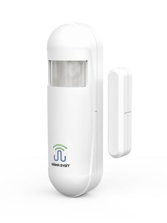
Product Picture


1 - 1) Sensitivity setting
This parameter is to set the detection sensitivity of the motion sensor. The smaller the value is and the higher the detection sensitivity is, the farther the detection range of the sensor is.Size: 1 byte
Default: 4
Minimum: 0
Maximum: 0
Possible values
| From | To | Desription |
|---|---|---|
| 0 | 99 | 0 is Max Sensitivity, 99 is Min Sensitivity |
2 - PIR Window Time Setting
PIR sensor detects the duration of the motion events. Within the scope of the time, if events meeting Parameter 3 occur, the sensor will confirm that it has detected the occurrence of the motion events.In theory, the greater this value is, the higher the sensitivity of the sensor is. Thus, it is not recommended for users to modify the setting of this parameter. Window time = ([setting] + 1) × 4s, (value range: 4s, 8s, 12s, 16s)Size: 1 byte
Default: 2
Minimum: 0
Maximum: 0
Possible values
| From | To | Desription |
|---|---|---|
| 0 | 3 | Window time = (Value + 1) x 4s; |
3 - PIR Pulse Counter Settings
Within the window time set by Parameter 2, when the number of pulses detected by the sensor reaches the value set by this parameter, the sensor will determine the occurrence of motion events. In theory, the higher the value is, the lower the sensitivity of the sensor is. It is not recommended for the user to modify the setting of this parameter. Number of pulses = [setting] + 1. So the value range of the parameter is as follows: 1, 2, 3, 4.Size: 1 byte
Default: 1
Minimum: 0
Maximum: 0
Possible values
| From | To | Desription |
|---|---|---|
| 0 | 3 | Pulse Counter = Value + 1 |
4 - PIR Blind Time Setting
BlindAfter the sensor detects a motion event, it will stop detecting the duration of the motion event. During this period, the sensor will not issue any command even if there is a motion event occurring in front of the PIR sensor. In theory, the higher the value is, the lower the power consumption of the sensor is. The time set by this parameter must be shorter than the time set by Parameter 9. Silence period = ([setting] + 1) x 0.5s.Thus, the value range of this parameter is as follows: 0.5s ~ 8s, with an interval of 0.5s.Size: 1 byte
Default: 15
Minimum: 0
Maximum: 0
Possible values
| From | To | Desription |
|---|---|---|
| 0 | 15 | Blind Time = (Value + 1) x 0.5s |
5 - PIR Detected Disable
The detection function of the motion sensor set by this parameter is disabled or not.'1'-motion detected function is enabled; '0'-motion detected function is disabled.Size: 1 byte
Default: 1
Minimum: 0
Maximum: 0
Possible values
| From | To | Desription |
|---|---|---|
| 0 | 1 | 0 - Disable, 1 - Enable |
6 - LED indicator Disable
This parameter is to set whether the sensor will open LED and other indication functions when detecting a motion event. '1'-LED indication is open. When the sensor detects a motion event, the LED will flash once; '0'-LED indication is closed. When the sensor detects a motion event, the LED will not flash. Setting of this parameter will not affect the LED indication of the sensor in other conditions.Size: 1 byte
Default: 1
Minimum: 0
Maximum: 0
Possible values
| From | To | Desription |
|---|---|---|
| 0 | 1 | 0 - Disable, 1 - Enable |
7 - Associated Control with Light Sensor Setting
This parameter sets whether to send the BASIC_SET command to the connected device based on the current brightness when there is a connected device in Connection Group 2.Parameters of BASIC_SET are determined by Parameter 8. '0'-Whether to send BASIC_SET command has nothing to do with the current environment brightness. As long as the sensor detects the occurrence of the motion event, the sensor will send BASIC_SET command to all devices of Connection Group 2 to control the motions of the device. '1'-When the current environment brightness is lower than the brightness value set by Parameter 11 and the sensor detects the occurrence of the motion event, the sensor will send the BASIC_SET command to all devices in Connection Group 2; If the current environment brightness is greater than or equal to the brightness value set by the parameter, the sensor will not send BASIC_SET command to all devices in Connection Group 2.Size: 1 byte
Default: 0
Minimum: 0
Maximum: 0
Possible values
| From | To | Desription |
|---|---|---|
| 0 | 1 | 0 - Disable, 1 - Enable |
8 - Setting of BASIC_SET parameter
This parameter defines the parameter value of BASIC_SET command so as to facilitate the control over different connected devices by the sensor. For example, if the connected device is a light, when the door magnet is detected to be open, this device will issue BASIC_SET command (the corresponding parameter is the set value of the parameter) to control the switch of the light.Size: 1 byte
Default: 100
Minimum: 0
Maximum: 0
Possible values
| From | To | Desription |
|---|---|---|
| 0 | 100 | 0 - Off, 100 - On(Corresponding to 0xFF), 1 ~ 99 is responding to multilevel value |
9 - Setting of BASIC_SET (0x00) time delay
This parameter sets the delay time of sending BASIC_SET = 0x00 (closing the connected device) command by the sensor to the connected device, the unit of which is: Seconds. The execution effect of this parameter is affected by Parameter 15. ◆ If Parameter 15 is set as '1' or an event related to '1', the setting of this parameter will be invalid. The time controlling the connected device is only associated with the time set by Parameter 10. When the sensor triggers Motion Clear, it will send BASIC_SET=0x00 automatically. ◆ If Parameter 15 is set as '2' or '3' or an event related to '2' or '3', then when a Door/Window Close event or a Tamper Clear event occurs, the sensor will send BASIC_SET=0x00 to close the connected device after delaying for an interval set by this parameter. ◆ If Parameter 15 is set as ’4 ~ 7, 9, 10’, when the event meeting the conditions triggers the sensor, it will issue BASIC_SET= (value of Parameter 8) to control the connected device and then send BASIC_SET=0x00 to close the connected device after delaying for an interval set by this parameter. If the delay time has not come but the measured result of the sensor has returned to normal, then it will trigger BASIC_SET = 0x00 to close the connected device automatically. ◆ If this parameter is set as '0', it means that the BASIC_SET = 0x00 command is issued immediately when the trigger event is removed. ◆ If this parameter is set as '32767', it means that the device does not send BASIC_SET = 0x00 command.Size: 2 bytes
Default: 30
Minimum: 0
Maximum: 0
Possible values
| From | To | Desription |
|---|---|---|
| 0 | 4095 | 0- No Delay; Other Value is Delay time (Second) |
| 32767 | 32767 | Not Send BASIC_SET = 0x00 |
10 - Delay time of clear the motion event
The time set by this parameter refers to: The duration from the time when the sensor detects the motion event to the time when the sensor completes the removal of the motion event alarm. If during this period, the sensor detects the occurrence of another motion event, the timer will start counting again.When the sensor removes the motion event alarm, the sensor will also send BASIC_SET(0x00) command to all devices in Connection Group 2.Size: 2 bytes
Default: 30
Minimum: 0
Maximum: 0
Possible values
| From | To | Desription |
|---|---|---|
| 0 | 4095 | Motion event clear time delay |
11 - Setting of light intensity value report
This parameter sets the conditions of the sensor detecting the environment brightness value and reporting it to the host. If the absolute value of the difference between the currently measured environment brightness value and that measured last time is greater than the value set by this parameter, the sensor will report the currently measured environment brightness value to the host, or otherwise the value will not be reported. In theory, the smaller the value is, the shorter the battery’s life is.Size: 2 bytes
Default: 50
Minimum: 0
Maximum: 0
Possible values
| From | To | Desription |
|---|---|---|
| 0 | 1000 | lux, the Differential value for Luminance Report. |
12 - Setting of light intensity threshold in the night
The values set by this parameter should make it clear whether the current time is night or daytime. If the currently measured environment brightness is greater than the set value of this parameter, it means that it is daytime currently; otherwise it is in the evening.Size: 2 bytes
Default: 50
Minimum: 0
Maximum: 0
Possible values
| From | To | Desription |
|---|---|---|
| 0 | 1000 | If the Light Intensity Value is less than this value, it will be considered to night. |
13 - Setting of temperature value report
This parameter sets the conditions of reporting the environmental temperature value currently measured by the temperature sensor to the host. If the absolute value of the difference between the currently measured environmental temperature value and that reported last time is greater than the value represented by the setting of this parameter, the sensor will report the currently measured environmental temperature value to the host, or otherwise the value will not be reported. In theory, the smaller the value is, the shorter the battery’s life is. Each value represents 0.1 Celsius degree. For example, if the default value is set as '5', then the temperature represented is 5 * 0.1 = 0.5 Celsius degree; It means that when the difference between the current temperature and the temperature reported last time is greater than 0.5 Celsius degree, the current temperature value will be reported to the host.Size: 1 byte
Default: 5
Minimum: 0
Maximum: 0
Possible values
| From | To | Desription |
|---|---|---|
| 0 | 100 | The Differential value for Temperature Report. (0.1 Celsius) |
14 - Interval of the sensors measured setting
This parameter sets the measurement interval of the optical sensor. The greater the set value of this parameter is, the longer the battery life is and the less frequently the brightness is reported to the host when Parameter 10 is met; The smaller the set value of the parameter is, the shorter the battery life will be accordingly and the more the brightness data reported to the host with Parameter 10 being met is. Unit: minSize: 1 byte
Default: 3
Minimum: 0
Maximum: 0
Possible values
| From | To | Desription |
|---|---|---|
| 1 | 127 | minute. the time interval for Sensor measurment |
15 - Setting of the trigger source for controlled the associated devices
This parameter sets to control connected devices in Group 2 by selecting a certain trigger event supported by the device. ◆0 – None of the following events will trigger BASIC_SET command to control the connected devices. ◆1 – When detecting a motion event (Motion), it will trigger BASIC_SET command to control the connected devices ◆2 – When detecting the doors or windows being opened (Open), it will trigger BASIC_SET command to control the connected devices ◆3 – When detecting the device being dismantled (Tamper), it will trigger BASIC_SET command to control the connected devices ◆4 – When the brightness is lower than the threshold set in 16, it will trigger BASIC_SET command to control the connected devices ◆5 – When the brightness is lower than the threshold set in 17, it will trigger BASIC_SET command to control the connected devices ◆6 – When the temperature is lower than the threshold set in 18, it will trigger BASIC_SET command to control the connected devices ◆7 – When the temperature is lower than the threshold set in 19, it will trigger BASIC_SET command to control the connected devices ◆ 8 – When Conditions 1 ~ 3 are met, it will trigger BASIC_SET command to control the connected devices ◆ 9 – When Conditions 4 ~ 5 are met, it will trigger BASIC_SET command to control the connected devices ◆10 – When Conditions 6 ~ 7 are met, it will trigger BASIC_SET command to control the connected devicesSize: 1 byte
Default: 0
Minimum: 0
Maximum: 0
Possible values
| From | To | Desription |
|---|---|---|
| 0 | 10 | The Trigger source number for BASIC_SET Command |
16 - Low light intensity threshold
When the environment brightness value is lower than the value set by this parameter, if the trigger source set by Parameter 15 is low brightness threshold alarm, the sensor will trigger BASIC_SET to control all connected devices in Connection Group 2.Size: 2 bytes
Default: 50
Minimum: 0
Maximum: 0
Possible values
| From | To | Desription |
|---|---|---|
| 0 | 1000 | Lux. Low threshold value for light intensity |
17 - High light intensity threshold
When the environment brightness value is higher than the value set by this parameter, if the trigger source set by Parameter 15 is high brightness threshold alarm, the sensor will trigger BASIC_SET to control all connected devices in Connection Group 2.Size: 2 bytes
Default: 2000
Minimum: 0
Maximum: 0
Possible values
| From | To | Desription |
|---|---|---|
| 1 | 32767 | Lux. High threshold value for light intensity |
18 - Low temperature threshold
When the environment temperature value is lower than the value set by this parameter, if the trigger source set by Parameter 15 is low temperature threshold alarm, the sensor will trigger BASIC_SET to control all connected devices in Connection Group 2.Size: 1 byte
Default: 0
Minimum: 0
Maximum: 0
Possible values
| From | To | Desription |
|---|---|---|
| -40 | 30 | celsius, Low temperature threshold Value |
19 - High temperature threshold
When the environment temperature value is lower than the value set by this parameter, if the trigger source set by Parameter 15 is low temperature threshold alarm, the sensor will trigger BASIC_SET to control all connected devices in Connection Group 2.Size: 1 byte
Default: 25
Minimum: 0
Maximum: 0
Possible values
| From | To | Desription |
|---|---|---|
| 0 | 80 | celsius. High temperature threshold value |
20 - Binary Sensor Report Enable
When this parameter is set as 1, then the reporting Binary Sensor Report function of the sensor will be open. When the door magnet, motion detection, or tamper event is triggered, in addition to reporting the Notification Report to the host, it will also report the Binary Sensor Report for the purpose of downward compatibility of the sensor.Size: 1 byte
Default: 0
Minimum: 0
Maximum: 0
Possible values
| From | To | Desription |
|---|---|---|
| 0 | 1 | 0 - Disable, 1 - Enable |
99 - Light Sensor Calibrated
Due to the differences in shell light transmittance and the influences of sensor installation position on the receiving of light by light sensor, there will be errors in the measurement of environment brightness values. This parameter provides correction methods used in different application environments so as to get as exact environment light intensity as possible. This method requires a standard illuminometer as the reference and it will add the sensor to Z-Wave network. The correction steps are as follows: a、 Restore this parameter to default value by the host. b、 Put the standard illuminometer and the sensor in the same position and ensure that the light exposed to them is largely equal. Record the reading on the standard illuminometer, namely Vs. The value measured by this sensor, namely Vm, will be sent to the host via Z-Wave network. Record Vm. The calibration coefficient of this sensor is: k = Vm / Vs. c、 Multiply k, the coefficient having obtained, by 1024, and then get an integer by rounding it. d、 Set the value obtained in step c in Parameter 13 via the host. Then the calibration is finished. Example: The reading of the illuminometer Vs = 2600, and the data measured by the sensor at the same time Vm = 300; Then, k = Vm / Vs = 300 / 2600 = 0.1153, multiply the result by 1024 k = 0.1153 * 1024 = 118.07, Round it, k = 118 And then the calibration will be finished after the value 118 is set in Parameter 99 by host.Size: 2 bytes
Default: 1024
Minimum: 0
Maximum: 0
Possible values
| From | To | Desription |
|---|---|---|
| 1 | 32767 | Light intensity value correct coefficient |
a) Ensure that the sensor is powered up correctly. b) Set Z-Wave Gateway entered inclusion mode. c) Press the tamper button on the back of the sensor for three times quickly within 1.5 seconds. Then the LED light will flash for 10 times with an interval of one second, which means that the sensor has entered the mode of networking and it is waiting for the gateway to complete the configuration.
a) Ensure that the sensor is powered up correctly. b) Set Z-Wave Gateway entered exclusion mode. c) Press the tamper button on the back of the sensor for three times quickly within 1.5 seconds. Then the LED light will flash for 10 times with an interval of 500ms, which means that the sensor has entered the mode of removing from the network and it is waiting for the host to complete the configuration.
First, press the both two tamper buttons on the both side of the device simultaneously and then power the sensor up, which will make it enter the factory testing mode. In this mode, no sensor function works, and the LED light will keep flashing. Exit from factory test mode: Power off and then power the socket on by un-pressing two buttons. And then it will enter the normal working mode.
Press the tamper button on the back of the sensor shortly. Then the LED will flash once. If the sensor has added in a Z-Wave network, the sensor will send WAKE_UP_INFORMATION message to the gateway. If the tamper button is pressed for three times quickly, the sensor will broadcast NODE_INFO messages.
a) Ensure that the sensor is powered up correctly. b) Remove the sensor cover on the top, press the tamper button on the top of the sensor three times quickly within 1.5s. Then sensor will erase all data and restore to the defaults and the LED will flash for 10times with an interval of 500ms. Note: This mode can also erase the network information of the sensor and make the device removed from the Z-Wave network that it has included. Please use this procedure only when the network primary controller is missing or otherwise inoperable.
| Type | Value(s) |
|---|
| Group | Type |
|---|---|
| Home Security | (Refer to parameters): State idle |
| Sensor type |
|---|
| Illuminance |