devolo
Devolo HC Switch FM
MT 02759
On/Off Power Switch
HW: 1 FW: 6.05:06.05
ZM5202
6.51.09
0x0175 (373)
0x0002 (2)
0x0052 (82)
ZC10-18036057
2018-03-14 16:26:38.127554
N/A
Enhanced 232 Slave
Always On Slave
The Devolo HC Switch FM is ideal for remotely controlling one light or electrical device (door lock, door opener, small appliances, etc.).
The Devolo HC Switch FM controls on/off function for one electrical device. It measures power consumption of the connected device, and can be paired with a digital temperature sensor (sold separately). It supports push-button/momentary switches and toggle switches (default). The connection of a digital temperature sensor means you can create complex scenes and control any device relative to a set temperature range. The Devolo HC Switch FM also acts as a Z-Wave repeater to improve the range and stability of the Z-Wave network.
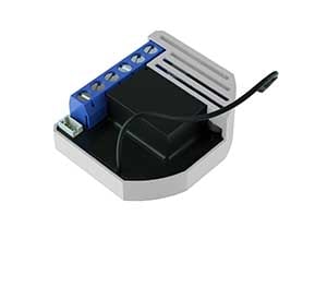
Product Picture


1 - In-wall Switch Type for Load 1 (Q⬆) to control I1
With this parameter, you can select between push-button (momentary) and on/off toggle switch types.Size: 1 byte
Default: 1
Minimum: 0
Maximum: 0
Possible values
| From | To | Desription |
|---|---|---|
| 0 | 0 | push-button (momentary) |
| 1 | 1 | on/off toggle switch |
2 - Input 2 contact type
With this parameter, input 2 contact type is defined.Size: 1 byte
Default: 0
Minimum: 0
Maximum: 0
Possible values
| From | To | Desription |
|---|---|---|
| 0 | 0 | NO (normally open) input type |
| 1 | 1 | NC (normally close) input type |
3 - Input 3 contact type
With this parameter, input 3 contact type is defined.Size: 1 byte
Default: 0
Minimum: 0
Maximum: 0
Possible values
| From | To | Desription |
|---|---|---|
| 0 | 0 | NO (normally open) input type |
| 1 | 1 | NC (normally close) input type |
10 - Activate / deactivate ALL ON / ALL OFF Functionality
Devolo Relay device responds to commands ALL ON / ALL OFSize: 2 bytes
Default: 255
Minimum: 0
Maximum: 0
Possible values
| From | To | Desription |
|---|---|---|
| 255 | 255 | ALL ON active, ALL OFF active |
| 0 | 0 | ALL ON not active, ALL OFF not active |
| 1 | 1 | ALL ON not active, ALL OFF active |
| 2 | 2 | ALL ON active, ALL OFF not active |
11 - Turn Load 1 (Q⬆) Off Automatically with Timer
If Load 1 (Q⬆) is ON, you can schedule it to turn OFF automatically after a period of time defined in this parameter. The timer is reset to zero each time the device receives an ON command, either remotely (from the gateway (hub) or associated device) or locally from the switch.Size: 2 bytes
Default: 0
Minimum: 0
Maximum: 0
Possible values
| From | To | Desription |
|---|---|---|
| 0 | 0 | Auto OFF Disabled |
| 1 | 32535 | 1 - 32535 seconds (or milliseconds – see Parameter no. 15) Auto OFF timer enabled for a given amount of seconds (or milliseconds) |
12 - Turn Load 1 (Q⬆) On Automatically with Timer
If Load (Q⬆) is OFF, you can schedule it to turn ON automatically after a period of time defined in this parameter. The timer is reset to zero each time the device receives an OFF command, either remotely (from the gateway (hub) or associated device) or locally from the switch.Size: 2 bytes
Default: 0
Minimum: 0
Maximum: 0
Possible values
| From | To | Desription |
|---|---|---|
| 0 | 0 | Auto ON Disabled |
| 1 | 32535 | 1 - 32536 seconds (or milliseconds – see Parameter no. 15) Auto ON timer enabled- for a given amount of seconds (or milliseconds). |
15 - Set Timer Units to Seconds or Milliseconds
Choose if you want to set the timer in seconds or milliseconds in parameters 11 and 12. Please note that the value for this parameter applies to settings for Q⬆ load in all of the above parameters (timer on / timer off).Size: 1 byte
Default: 0
Minimum: 0
Maximum: 0
Possible values
| From | To | Desription |
|---|---|---|
| 0 | 0 | timer set in seconds |
| 1 | 1 | timer set in milliseconds |
30 - Restore on/off status for Q⬆ load after power failure
This parameter determines if on/off status is saved and restored for the load Q⬆ after power failure.Size: 1 byte
Default: 0
Minimum: 0
Maximum: 0
Possible values
| From | To | Desription |
|---|---|---|
| 0 | 0 | device saves last on/off status and restores it after a power failure. |
| 1 | 1 | device does not save on/off status and does not restore it after a power failure, it remains off. |
40 - Watt Power Consumption Reporting Threshold for Q⬆ Load
Choose by how much power consumption needs to increase or decrease to be reported. Values correspond to percentages so if 10 is set (by default), the device will report any power consumption changes of 10% or more compared to the last reading. NOTE: Power consumption needs to increase or decrease by at least 1 Watt to be reported, REGARDLESS of percentage set in this parameter.Size: 1 byte
Default: 10
Minimum: 0
Maximum: 0
Possible values
| From | To | Desription |
|---|---|---|
| 0 | 0 | Power consumption reporting disabled |
| 1 | 100 | 1% - 100% Power consumption reporting enabled. New value is reported only when Wattage in real time changes by more than the percentage value set in this parameter compared to the previous Wattage reading, starting at 1% (the lowest value possible). |
42 - Watt Power Consumption Reporting Time Threshold for Q⬆ Load
Set value refers to the time interval with which power consumption in Watts is reported (0 – 32535 seconds). If 300 is entered (by default), energy consumption reports will be sent to the gateway (hub) every 300 seconds (or 5 minutes).Size: 2 bytes
Default: 300
Minimum: 0
Maximum: 0
Possible values
| From | To | Desription |
|---|---|---|
| 0 | 0 | Power consumption reporting disabled |
| 1 | 32535 | 1 - 32535 seconds. Power consumption reporting enabled. Report is sent according to time interval (value) set here. |
63 - Choose Normally Closed or Normally Open for Q⬆ Load
Set value determines the type of the device connected to the Q⬆ output. The output type can be normally open (NO) or normally closed (NC).Size: 1 byte
Default: 0
Minimum: 0
Maximum: 0
Possible values
| From | To | Desription |
|---|---|---|
| 0 | 0 | When switch/device is off the output is 0V (NO). |
| 1 | 1 | When switch/device is off the output is 230V (NC). |
100 - Enable / Disable Endpoint I2 or select the Notification Type and the Notification Event
Choose whether the Endpoint I2 is disabled (and not shown on the UI) or enabled (and displayed on the UI). By enabling this endpoint (setting it to be either a notification sensor or a binary sensor), the user also selects a Notification Type and a Notification Event for which notification reports will be sent (in case the endpoint is configured as a notification sensor). Endpoint device type selection: -notification sensor (1 - 6): GENERIC_TYPE_SENSOR_NOTIFICATION, SPECIFIC_TYPE_NOTIFICATION_SENSOR sensor binary (9): GENERIC_TYPE_SENSOR_BINARY, SPECIFIC_TYPE_NOT_USED Values (size is 1 byte dec): NOTE 1: After changing the values of the parameter, first exclude the device (without setting the parameters to their default values), then wait at least 30 seconds to re-include the device! NOTE 2: When the parameter is set to value 9 the notifications are sent for the Home Security notification type.Size: 1 byte
Default: 0
Minimum: 0
Maximum: 0
Possible values
| From | To | Desription |
|---|---|---|
| 1 | 1 | Home Security; Motion Detection, unknown location |
| 2 | 2 | CO; Carbon Monoxide detected, unknown location |
| 3 | 3 | CO2; Carbon Dioxide detected, unknown location |
| 4 | 4 | Water Alarm; Water Leak detected, unknown location |
| 5 | 5 | Heat Alarm; Overheat detected, unknown location |
| 6 | 6 | Smoke Alarm; Smoke detected, unknown location |
| 0 | 0 | Endpoint, I2 disabled |
| 9 | 9 | Sensor binary |
101 - Enable / Disable Endpoint I3 or select the Notification Type and the Notification Event
Choose whether the Endpoint I3 is disabled (and not shown on the UI) or enabled (and displayed on the UI). By enabling this endpoint (setting it to be either a notification sensor or a binary sensor), the user also selects a Notification Type and a Notification Event for which notification reports will be sent (in case the endpoint is configured as a notification sensor). Endpoint device type selection: -notification sensor (1 - 6): GENERIC_TYPE_SENSOR_NOTIFICATION, SPECIFIC_TYPE_NOTIFICATION_SENSOR -sensor binary (9): GENERIC_TYPE_SENSOR_BINARY, SPECIFIC_TYPE_NOT_USED NOTE 1: After changing the values of the parameter, first exclude the device (without setting the parameters to their default values), wait at least 30 seconds and then re-include the device! NOTE 2: When the parameter is set to the value 9 the notifications are sent for the Home Security notification type.Size: 1 byte
Default: 0
Minimum: 0
Maximum: 0
Possible values
| From | To | Desription |
|---|---|---|
| 1 | 1 | Home Security; Motion Detection, unknown location |
| 2 | 2 | CO; Carbon Monoxide detected, unknown location |
| 3 | 3 | CO2; Carbon Dioxide detected, unknown location |
| 4 | 4 | Water Alarm; Water Leak detected, unknown location |
| 5 | 5 | Heat Alarm; Overheat detected, unknown location |
| 6 | 6 | Smoke Alarm; Smoke detected, unknown location |
| 0 | 0 | Endpoint, I2 disabled |
| 9 | 9 | Sensor binary |
110 - Temperature Sensor Offset Settings
Set value is added to or subtracted from the actual measured value to adjust the temperature report sent by an external sensor (sold separately). This parameter only applies to Celcius temperature unit (the Fahrenheit unit is currently not supported).Size: 2 bytes
Default: 32536
Minimum: 0
Maximum: 0
Possible values
| From | To | Desription |
|---|---|---|
| 32536 | 32536 | Offset is 0 degrees. |
| 1 | 100 | Where 1 stands for 0.1 and 100 stands for 10.00 degrees added to the actual measurement |
| 1001 | 1100 | Where 1001 stands for -0.1 degrees and 1100 stands for -10.0 degrees subtracted from the actual measurement |
120 - Temperature Sensor Reporting Threshold
If an external digital temperature sensor (sold separately) is connected to the device, it reports temperature readings based on the threshold defined in this parameter. This parameter only applies to the degrees temperature unit (the Fahrenheit unit is currently not supported).Size: 1 byte
Default: 5
Minimum: 0
Maximum: 0
Possible values
| From | To | Desription |
|---|---|---|
| 5 | 5 | 0.5 degrees Celsius |
| 0 | 0 | Reporting disabled |
| 1 | 127 | Where 1 stands for 0.1 and 127 stands for 12.7 degrees |
AUTOMATICALLY ADDING THE DEVICE TO A Z-WAVE NETWORK 1. Enable add/remove mode on your Z-Wave gateway (hub) 2. Connect the device to the power supply (with the temperature sensor already connected – sold separately*). 3. Auto-inclusion will be initiated within 5 seconds of connection to the power supply and the device will automatically enroll in your network MANUALLY ADDING THE DEVICE TO A Z-WAVE NETWORK 1. Enable add/remove mode on your Z-Wave gateway (hub) 2. Connect the device to the power supply (with the temperature sensor already connected*) 3. Toggle the switch connected to the I1 terminal 3 times within 3 seconds OR If the device is powered by 24 V SELV supply, press and hold the S (Service) button for at least 2 seconds 4. A new multi-channel device will appear on your dashboard *If connecting the temperature sensor, switch off the power supply and make sure the device is excluded from your network BEFORE connecting the sensor. Make sure the device is excluded from your network before connecting the temperature sensor. Switch off the power supply, connect the temperature sensor, and re-include the device to your network.
REMOVAL FROM A Z-WAVE NETWORK • Connect module to power supply • bring module within maximum 1 meter (3 feet) of the main controller, • enable add/remove mode on main controller If push button I1 is pressed three times within 5s (or service button S is pressed more than 2 and less than 6 seconds) module is excluded, but configuration parameters are not set to default values.
FACTORY RESET • Connect module to power supply • bring module within maximum 1 meter (3 feet) of the main controller, • enable add/remove mode on main controller • press push button I1 five times within 5s (5 times change switch state within 5 seconds) in the first 60 seconds after the module is connected to the power supply or • press service button S (only applicable for 24 V SELV supply voltage) for more than 6 second. By this function all parameters of the module are set to default values and own ID is deleted. *Please use this procedure only when the network primary controller is missing or otherwise inoperable.
| Type | Value(s) |
|---|
| Group | Type |
|---|---|
| Smoke Alarm | State Idle |
| CO Alarm | (Refer to parameters): State idle |
| CO2 Alarm | Sensor status: Carbon dioxide detected (location provided) |
| Heat Alarm | (Refer to parameters): State idle |
| Water Alarm | (Refer to parameters): State idle |
| Home Security | (Refer to parameters): State idle |
| Power Management | (Refer to parameters): State idle |
| Gas alarm | (Refer to parameters): State idle |
| Sensor type |
|---|
| Air Temperature |
| Meter type |
|---|
| Electric Meter Consumption |