SE Devices
Multifunction Switch
FMS
Wall Controller
HW: 30 FW: 3.00:03.00
ZM5202
6.71.01
0x024F (591)
0x0003 (3)
0x1002 (4098)
ZC10-18026000
2018-01-22 04:40:38.889425
N/A
Enhanced 232 Slave
Always On Slave
Four button Z-Wave Plus Wall Controller for controlling Light Zones, Heating Zones and Central Scenes.
The Multifunction Switch is a Z-Wave Plus mains powered Wallbox mountable Wall Controller. It can be configured to control up to Four separate Light Zones or Central Scenes. Each Light Zone can consist of both Dimmers and Switches. The device can be combined with a Back Unit, which provide local Switch or Dimmer functionality. Room and Floor temperature sensors can also be connected to the device, which enables the device to function as a head-less Thermostat. The Thermostat is fully controllable from a Z-Wave Controller, and can control both a Local and Remote heating relay.
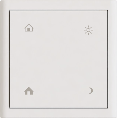
Product Picture


4 - Safety Activate Delay
Safety Mode is activated after the configured number of seconds has elapsed. It will start by turning OFF the Back Unit when activated. A 0 value Disables Safety Mode. The MAX limit is 32767 seconds (9 hours, 6 minutes and 7 seconds). The minimum Actication delay is 60 seconds, and values from 1 to 59 will automatically be translated to a 60 second delay.Size: 2 bytes
Default: 0
Minimum: 0
Maximum: 0
Possible values
| From | To | Desription |
|---|---|---|
| 0 | 32767 | Safety Activate Delay in seconds |
5 - Safety OFF Period
The number of seconds to stay in OFF mode when Safety is activated. The Back unit turns ON when the timer have elapsed. If value is 0, the Back Unit will not turn back ON. The MAX limit is 32767 seconds (9 hours, 6 minutes and 7 seconds). A 60 second minimum period applies.Size: 2 bytes
Default: 600
Minimum: 0
Maximum: 0
Possible values
| From | To | Desription |
|---|---|---|
| 0 | 32767 | Safety OFF Period in seconds |
6 - Safety ON Period
The number of seconds to stay in ON mode when Safety is activated. The Back Unit turns back OFF when the timer have elapsed (and continues to turn ON and OFF alternately). If value is 0, the Back Unit WILL NOT turn ON at all. The MAX limit is 32767 seconds (9 hours, 6 minutes and 7 seconds). A 60 second minimum period applies.Size: 2 bytes
Default: 300
Minimum: 0
Maximum: 0
Possible values
| From | To | Desription |
|---|---|---|
| 0 | 32767 | Safety ON Period in seconds |
10 - Dimming Speed
Defines the "fade" time when setting a dim level from a controller. Fade time is defined as the time it takes to dim from MIN level to MAX level, which means an increase of 10% in light level takes 1/10th of the configured time. The value defines the dim time in 1/100'th of a second, which means a value of 200 means the Dimming Speed is 2.0 seconds from MIN to MAX. Max time is 327.67 seconds (around 5.5 minutes). Values below 300 (0.3 seconds) are ignored¸ and values below 1000 (1 second) are discouraged.Size: 1 byte
Default: 200
Minimum: 0
Maximum: 0
Possible values
| From | To | Desription |
|---|---|---|
| 30 | 32767 | Dimmer Speed in 1/100th of a Second |
11 - Dimmer Mode
Defines if Dimmer should operate in Leading or Tailing Edge mode. Most Lights work quite OK in the default Leading Edge mode, but this mode also usually cause some noise from the dimmer unit. During installation it is therefore recommended to try TE mode, and use this if the Light operates properly. Tailing Edge mode is known to cause instability in some type of Lights! This configuration does not have an effect on 1-10V Dimmer Back Units! 0 = Leading Edge Mode (LE) 1 = Tailing Edge Mode (TE)Size: 1 byte
Default: 0
Minimum: 0
Maximum: 0
Possible values
| From | To | Desription |
|---|---|---|
| 0 | 1 | Dimmer Operation Mode |
12 - Maximum Level
The Maximum Light level of the dimmer. Typically there is no visible difference when the dimming level reaches a point in the range 75 - 90, and the installer should set this value to the lowest value where no change is visible. The default value of 90 is usually OK. Range 1-99.Size: 1 byte
Default: 90
Minimum: 0
Maximum: 0
Possible values
| From | To | Desription |
|---|---|---|
| 1 | 99 | Maximum Dimmer Level |
13 - Minimum Level
The Minimum Light Level of the dimmer. This should be adjusted so the controlled Light is still ON and stable. Remember that LED type lights may work if dimmed down to a low value, but may not start if the light is turned OFF and ON again. Range 1-99.Size: 1 byte
Default: 12
Minimum: 0
Maximum: 0
Possible values
| From | To | Desription |
|---|---|---|
| 1 | 99 | Minimum Dimmer Level |
14 - Button Mode
Controls the operation mode of the buttons. Valid configuration values are: 0 – Single Switch Mode (default) 1 – Dual Switch Mode 2 – Quadruple Switch Mode 3 – Legacy Scenario Mode 4 – Central Scene Controller Mode (See detailed description in manual)Size: 1 byte
Default: 0
Minimum: 0
Maximum: 0
Possible values
| From | To | Desription |
|---|---|---|
| 0 | 4 | Set Button Mode |
15 - Light Zone Control Mode
Controls if the Light Zones should operate in Switch or Dimmer Mode (only used in Button Modes 0, 1 and 2): 0 – All Light Zones in Dimmer Mode (default) 1 – All Light Zones in Switch Mode (default with Relay back unit) To control Light Zones mode individually, add any of the following values to enable switch mode individually (dimmer is default): 2 – Light Zone 1 Switch Mode 4 – Light Zone 2 Switch Mode 8 – Light Zone 3 Switch Mode 16 – Light Zone 4 Switch Mode Example: A value of 10 (8 + 2) enables switch mode in Light Zone 1 and 3.Size: 1 byte
Default: 0
Minimum: 0
Maximum: 0
Possible values
| From | To | Desription |
|---|---|---|
| 0 | 1 | Common Mode for all Light Zones |
| 2 | 30 | Switch Mode for individual Light Zones |
17 - Back Unit Role
Configures the Role of the Back Unit, which dictates what Local functionality controls it. Valid configuration values are: 0 - The Thermostat will control the Back Unit (if the back unit is a dimmer, then this value has no effect as Thermostats requires a relay to function) 1 - The Light Control feature (buttons) will control the Back Unit. 2 - Disconnected mode means the Back Unit is not controlled by any local UI or features, and can only be controlled via Z-Wave End-Point 5 (or non-channel encapsulated commands).Size: 1 byte
Default: 1
Minimum: 0
Maximum: 0
Possible values
| From | To | Desription |
|---|---|---|
| 0 | 2 | Selected Back Unit Role |
18 - Back Unit Light Zone
Selects which Light Zone the Back Unit should be assigned to. Possible values are: 1 – Light Zone 1 (Button and Z-Wave) (default) 2 – Light Zone 2 (Button and Z-Wave) 3 – Light Zone 3 (Button and Z-Wave) 4 – Light Zone 4 (Button and Z-Wave) This can be used to assign the back unit control to any of the Multiswitch buttons (Light Zone 1 - 4). This does not have any effect however when the BU role is set to Thermostat or Disconnected!Size: 1 byte
Default: 1
Minimum: 0
Maximum: 0
Possible values
| From | To | Desription |
|---|---|---|
| 1 | 4 | Selected Back Unit Light Zone |
32 - Thermostat Set Point Max
Maximum Heat Set Point the Thermostat is allowed to be set to. If the Thermostat is used for Floor Heating, please make sure that this value is configured to the same value as (or lower than) the Max Floor Temperature. Given in 1/10 of a degree Celcius, which means a value of 300 means 30 degrees C. Range: 0 – 500 (0-50 degrees).Size: 2 bytes
Default: 270
Minimum: 0
Maximum: 0
Possible values
| From | To | Desription |
|---|---|---|
| 0 | 500 | Set Point Max in 1/10th of a degree Celcius |
34 - Thermostat Set Point Min
Minimum Heat Set Point the Thermostat is allowed to be set to. Given in 1/10 of a degree Celcius, which means a value of 50 means 5 degrees C. Range: 0 – 500 (0-50 degrees).Size: 2 bytes
Default: 50
Minimum: 0
Maximum: 0
Possible values
| From | To | Desription |
|---|---|---|
| 0 | 500 | Set Point Min in 1/10th of a degree Celcius |
36 - Thermostat Control Resend Interval
Defines the interval between each time the Thermostat will repeat its last control command. This is used in combination with the Relay Safety configuration when controlling external Relays. If the Thermostat should fail, it would then stop sending control commands which in turn means the Relay will turn itself OFF after the safety mode delay has expired. This insures that heating will not be left ON indefinitely in failure situations. Range: 60 – 32767 secondsSize: 2 bytes
Default: 3600
Minimum: 0
Maximum: 0
Possible values
| From | To | Desription |
|---|---|---|
| 0 | 32767 | Resend Interval in seconds |
37 - Thermostat Minimum On/Off Interval
This configuration defines the minimum interval the controlled Thermostat Relays will be ON and OFF. This is a feature intended to avoid turning control relays ON and OFF too frequently, which should insure a better lifetime of controlled relays. The default value is 5 minutes, which is OK for most electrical heating control. If used to control Water based heating, the value MUST be adjusted in accordance with the manufacturers specifications. Range: 60 – 32767 secondsSize: 2 bytes
Default: 300
Minimum: 0
Maximum: 0
Possible values
| From | To | Desription |
|---|---|---|
| 60 | 32767 | Minimum On/Off interval in seconds |
38 - Thermostat Floor Temp Max
Max floor temperature if a local floor sensor is connected. If the Floor Sensor reads a temperature Higher than the configured value, it will immediately turn the relay (or any associated relays) OFF. The relay will stay off until the temperature sinks below this value, and the Thermostat issues it's next control command. Disabled if zero (0) value, or if no floor sensor is connected. The value is given as 1/10th of a degree Celcius. Range: 0 – 500 (0-50 degrees). NOTE! MAX 27 degrees is recommended for Wooden Floors! NOTE! This function is always active as long as a Floor Sensor is connected, regardless of the sensor configuration described below.Size: 2 bytes
Default: 270
Minimum: 0
Maximum: 0
Possible values
| From | To | Desription |
|---|---|---|
| 0 | 500 | Floor Temp Max in 1/10th of a degree Celcius |
40 - Temperature Sensor Select
Defines which temperature Sensor should be used for Heating Control. The default value is Both (3), which should work well in most scenarios (even when only a Floor or Room sensor is present). If both a Room and Floor sensor is used, the Thermostat will always control heating based on the lowest temperature reading of the two, to insure a comfortable floor temperature even if the room is already warm enough. If this is not wanted, the Thermostat should be configured to use the Room sensor Only. NOTE! The Floor Max Temperature feature will ALWAYS be active as long as a floor sensor is available, even if the Thermostat is configured to only use the Room Sensor. 1 - Local Room - Use temperature from Locally connected Room sensor ONLY. Max Floor Temp protection is still active as long as a floor sensor is available. 2 - Local Floor - Use temperature from Locally connected Floor sensor ONLY 3 - Both (auto) - Use temperature from Locally connected Floor AND Room sensor if available (Default).Size: 1 byte
Default: 3
Minimum: 0
Maximum: 0
Possible values
| From | To | Desription |
|---|---|---|
| 1 | 3 | Temperature Sensor Select |
44 - Cold Start Minimum Level
Sets the minimum level the Dimmer should go to when the light is switched ON. This is typically used for LED lamps which does not switch ON correctly when the dimming level is at the Minimum. See detailed description below.Size: 1 byte
Default: 12
Minimum: 0
Maximum: 0
Possible values
| From | To | Desription |
|---|---|---|
| 1 | 99 | Cold Start Minimum Level |
64 - Temperature Report Inteval
Defines the Periodic Report interval for temperature readings. This can be configured to a minimum of 60 seconds and maximum of (32767 seconds. A 0 value disables the Interval based Periodic reporting, and any value below 60 results in a 60 second interval.Size: 2 bytes
Default: 600
Minimum: 0
Maximum: 0
Possible values
| From | To | Desription |
|---|---|---|
| 0 | 32767 | Report Interval in seconds |
66 - Temperature Report Threshold
Defines a temperature change threshold where a temperature report is sent regardless of the Report Interval. This also works if the report interval is disabled. The value is given in 1/10 of a degree celsius, and can be in the range 1-127. A zero value disables the Threshold.Size: 1 byte
Default: 10
Minimum: 0
Maximum: 0
Possible values
| From | To | Desription |
|---|---|---|
| 0 | 127 | Report Threshold in 1/10th of a degree Celcius |
67 - Thermostat On∕Off Interval Override Threshold
Defines a temperature threshold at which the configured On/Off interval is overridden and the Heating relay state will change regardless. The value is given in 1/10th of a degree, supporting a max threshold of 12.7 degrees celcius. A Zero (0) value disables this feature (the default)Size: 1 byte
Default: 0
Minimum: 0
Maximum: 0
Possible values
| From | To | Desription |
|---|---|---|
| 0 | 127 | Temperature Threshold in 1/10th of a degree Celcius |
80 - Button LED Mode
Controls the operation of the LEDs. Possible values are: 0 – LEDs are always OFF (default) 1 – Momentary ON 2 – Stable ON The LED operation is described in details in the User Manual, and also depends on the Button Mode configuration.Size: 1 byte
Default: 0
Minimum: 0
Maximum: 0
Possible values
| From | To | Desription |
|---|---|---|
| 0 | 2 | Selected LED Mode |
240 - Floor Sensor Temperature Offset
Defines an offset to the Floor Temperature, given as a signed integer at 1/10 of a degree celcius. This provides an offset range of –12.8 to +12.7 degrees celcius (-128 to 127).Size: 1 byte
Default: 0
Minimum: 0
Maximum: 0
Possible values
| From | To | Desription |
|---|---|---|
| -128 | 127 | Temperature Offset in 1/10th of a degree Celcius |
241 - Room Sensor Temperature Offset
Defines an offset to the Room Temperature, given as a signed integer at 1/10 of a degree celcius. This provides an offset range of –12.8 to +12.7 degrees celcius (-128 to 127).Size: 1 byte
Default: 0
Minimum: 0
Maximum: 0
Possible values
| From | To | Desription |
|---|---|---|
| -128 | 127 | Temperature Offset in 1/10th of a degree Celcius |
Push and Hold both Lower buttons simultaneously for 5 seconds. Inclusion is indicated by the LEDs flashing in a ""U"" shaped pattern.
Push and Hold both Lower buttons simultaneously for 5 seconds. Exclusion is indicated by the LEDs flashing in a ""U"" shaped pattern.
Push and Hold both Left buttons simultaneously for 15 seconds, until the Lower Left LED starts blinking. Push and Hold the Lower Right button to confirm Factory Reset. The procedure can be aborted at any time, and will also be aborted if any other button than the Lower Right is pushed after the initial 15 second push and hold. WARNING! Executing a Factory Reset will set all configuration to factory defaults, and remove the device from the Z-Wave network. As all configuration is reset, the device may stop operating as intended and may require a re-configuration. Please use this procedure only when the network primary controller is missing or otherwise inoperable.
The Multifunction Switch is capable of controlling local loads via a modular Back Unit. The back unit can be mounted and connected to mains electricity inside a Electrical Wall box. Two types of Relay and Dimmer Back Units are currently available. The maximum controllable local load are specified in each Back Unit product sheets.
Push and Hold both Lower buttons simultaneously for 5 seconds. Inclusion is indicated by the LEDs flashing in a ""U"" shaped pattern.
Push and Hold both Lower buttons simultaneously for 5 seconds. Exclusion is indicated by the LEDs flashing in a ""U"" shaped pattern.
| Type | Value(s) |
|---|
| Meter type |
|---|
| Electric Meter Consumption |