FIBARO
FIBARO Single Switch 2
FGS-213
On/Off Power Switch
HW: 3 FW: 3.03
ZM5101
6.51.07
0x010F (271)
0x0403 (1027)
0x1000 (4096)
ZC10-18015919
2017-12-20 01:15:58.101103
N/A
Enhanced 232 Slave
Always On Slave
FIBARO Single Switch 2 is designed to turn electrical devices on and off and to measure their power and energy consumption.
The remotely operated FIBARO Single Switch 2 is designed to turn electrical devices on and off and to measure their power and energy consumption. The compact size of the device makes it the world's smallest of its type and allows for the product to be installed in wall switch boxes or housings. FIBARO Single Switch 2 can be controlled either via Z-Wave network or with a wall switch through a direct connection.
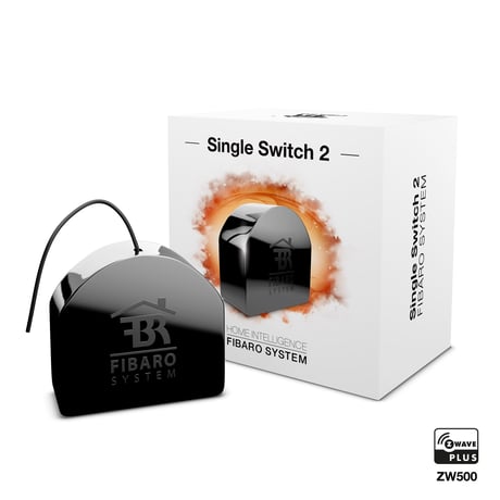
Product Picture


9 - Restore state after power failure
This parameter determines if the device will return to state prior to the power failure after power is restored. 0 - the device does not save the state prior to the power failure and returns to „off” position 1 - the device restores its state prior to the power failureSize: 1 byte
Default: 1
Minimum: 0
Maximum: 0
Possible values
| From | To | Desription |
|---|---|---|
| 0 | 0 | the device does not save the state prior to the power failure and returns to „off” position |
| 1 | 1 | the device restores its state prior to the power failure |
10 - First channel - operating mode
This parameter allows to choose operating for the 1st channel controlled by the S1 switch. 0 - standard operation 1 - delay ON function 2 - delay OFF function 3 - auto ON function 4 - auto OFF function 5 - flash functionSize: 1 byte
Default: 0
Minimum: 0
Maximum: 0
Possible values
| From | To | Desription |
|---|---|---|
| 0 | 0 | standard operation |
| 1 | 1 | delay ON function |
| 2 | 2 | delay OFF function |
| 3 | 3 | auto ON function |
| 4 | 4 | auto OFF function |
| 5 | 5 | flash function |
11 - First channel - reaction to switch for delay/auto ON/OFF modes
This parameter determines how the device in timed mode reacts to pushing the switch connected to the S1 terminal. 0 - cancel mode and set target state 1 - no reaction to switch - mode runs until it ends 2 - reset timer - start counting from the beginningSize: 1 byte
Default: 0
Minimum: 0
Maximum: 0
Possible values
| From | To | Desription |
|---|---|---|
| 0 | 0 | cancel mode and set target state |
| 1 | 1 | no reaction to switch - mode runs until it ends |
| 2 | 2 | reset timer - start counting from the beginning |
12 - First channel - time parameter for delay/auto ON/OFF modes
This parameter allows to set time parameter used in timed modes. 0 (0.1s), 1-32000 (1-32000s, 1s step) - time parameterSize: 2 bytes
Default: 50
Minimum: 0
Maximum: 0
Possible values
| From | To | Desription |
|---|---|---|
| 0 | 0 | 0.1s |
| 1 | 32000 | 1-32000s, 1s step |
13 - First channel - pulse time for flashing mode
This parameter allows to set pulse time used in flashing mode. 1-32000 (0.1-3200.0s, 0.1s step) - time parameterSize: 2 bytes
Default: 5
Minimum: 0
Maximum: 0
Possible values
| From | To | Desription |
|---|---|---|
| 1 | 32000 | (0.1-3200.0s, 0.1s step) - time parameter |
20 - Switch type
This parameter as what type the device should treat the switch connected to the S1 and S2 terminals. 0 - momentary switch 1 - toggle switch (contact closed - ON, contact opened - OFF) 2 - toggle switch (device changes status when switch changes status)Size: 1 byte
Default: 2
Minimum: 0
Maximum: 0
Possible values
| From | To | Desription |
|---|---|---|
| 0 | 0 | momentary switch |
| 1 | 1 | toggle switch (contact closed - ON, contact opened - OFF) |
| 2 | 2 | toggle switch (device changes status when switch changes status) |
21 - Flashing mode - reports
This parameter allows to define if the device sends reports during the flashing mode. 0 - the device does not send reports 1 - the device sends reportsSize: 1 byte
Default: 0
Minimum: 0
Maximum: 0
Possible values
| From | To | Desription |
|---|---|---|
| 0 | 0 | the device does not send reports |
| 1 | 1 | the device sends reports |
27 - Associations in Z-Wave network security mode
This parameter defines how commands are sent in specified association groups: as secure or non-secure. Parameter is active only in Z-Wave network security mode. This parameter does not apply to 1st „Lifeline” group. 1 - 2nd group sent as secure 2 - 3rd group sent as secure 4 - 4th group sent as secure 8 - 5th group sent as secure NOTE Parameter 27 values may be combined, e.g. 1+2=3 means that 2nd & 3rd groups are sent as secure.Size: 1 byte
Default: 15
Minimum: 0
Maximum: 0
Possible values
| From | To | Desription |
|---|---|---|
| 1 | 1 | 2nd group sent as secure |
| 2 | 2 | 3rd group sent as secure |
| 4 | 4 | 4th group sent as secure |
| 8 | 8 | 5th group sent as secure |
28 - S1 switch - scenes sent
This parameter determines which actions result in sending scene assigned to them. 1 - Key pressed 1 time 2 - Key pressed 2 time 4 - Key pressed 3 time 8 - Key Hold Down and Key Released NOTE Parameter 28 values may be combined, e.g. 1+2=3 means that scenes for single and double click are sent.Size: 1 byte
Default: 0
Minimum: 0
Maximum: 0
Possible values
| From | To | Desription |
|---|---|---|
| 1 | 1 | Key pressed 1 time |
| 2 | 2 | Key pressed 2 time |
| 4 | 4 | Key pressed 3 time |
| 8 | 8 | Key Hold Down and Key Released |
29 - S2 switch - scenes sent
This parameter determines which actions result in sending scene IDs assigned to them. 1 - Key pressed 1 time 2 - Key pressed 2 times 4 - Key pressed 3 times 8 - Key Hold Down and Key Released NOTE Parameter 29 values may be combined, e.g. 1+2=3 means that scenes for single and double click are sent.Size: 1 byte
Default: 0
Minimum: 0
Maximum: 0
Possible values
| From | To | Desription |
|---|---|---|
| 1 | 1 | Key pressed 1 time |
| 2 | 2 | Key pressed 2 times |
| 4 | 4 | Key pressed 3 times |
| 8 | 8 | Key Hold Down and Key Released |
30 - S1 switch - associations sent to 2nd and 3rd association groups
This parameter determines which actions are ignored when sending commands to devices associated in 2nd and 3rd association group. All actions are active by default. 1 - ignore turning ON with 1 click of the switch 2 - ignore turning OFF with 1 click of the switch 4 - ignore holding and releasing the switch* 8 - ignore double click of the switch** NOTE Parameter 30 values may be combined, e.g. 1+2=3 means that associations for turning ON and OFF are not sent. NOTE *Hold and release is inactive when parameter 20 is set to 1 or 2. **Double click is inactive when parameter 20 is set to 1.Size: 1 byte
Default: 0
Minimum: 0
Maximum: 0
Possible values
| From | To | Desription |
|---|---|---|
| 1 | 1 | ignore turning ON with 1 click of the switch |
| 2 | 2 | ignore turning OFF with 1 click of the switch |
| 4 | 4 | ignore holding and releasing the switch* |
| 8 | 8 | ignore double click of the switch** |
31 - S1 switch - Switch ON value sent to 2nd and 3rd association groups
This parameter defines value sent with Switch ON command to devices associated in 2nd and 3rd association group. 0-255 - sent valueSize: 2 bytes
Default: 255
Minimum: 0
Maximum: 0
Possible values
| From | To | Desription |
|---|---|---|
| 0 | 255 | sent value |
32 - S1 switch - Switch OFF value sent to 2nd and 3rd association groups
This parameter defines value sent with Switch OFF command to devices associated in 2nd and 3rd association group. 0-255 - sent value NOTE Setting parameters 31-33, 36-38 to appropriate value should result in: 0 - turning off associated devices 1-99 - forcing level of associated devices 255 - setting associated devices to the last remembered state or turning them onSize: 2 bytes
Default: 0
Minimum: 0
Maximum: 0
Possible values
| From | To | Desription |
|---|---|---|
| 0 | 255 | sent value |
33 - S1 switch - Double Click value sent to 2nd and 3rd association groups
This parameter defines value sent with Double Click command to devices associated in 2nd and 3rd association group. 0-255 - sent valueSize: 2 bytes
Default: 99
Minimum: 0
Maximum: 0
Possible values
| From | To | Desription |
|---|---|---|
| 0 | 255 | sent value |
35 - S2 switch - associations sent to 4th and 5th association groups
This parameter determines which actions result in sending commands to devices associated in 4th and 5th association group. All actions are active by default. 1 - ignore turning on with 1 click of the switch 2 - ignore turning off with 1 click of the switch 4 - ignore holding and releasing the switch* 8 - ignore double click of the switch** NOTE Parameter 35 values may be combined, e.g. 1+2=3 means that associations for turning ON and OFF are not sent. NOTE *Hold and release is inactive when parameter 20 is set to 1 or 2. **Double click is inactive when parameter 20 is set to 1.Size: 1 byte
Default: 0
Minimum: 0
Maximum: 0
Possible values
| From | To | Desription |
|---|---|---|
| 1 | 1 | ignore turning on with 1 click of the switch |
| 2 | 2 | ignore turning off with 1 click of the switch |
| 4 | 4 | ignore holding and releasing the switch* |
| 8 | 8 | ignore double click of the switch** |
36 - S2 switch - Switch ON value sent to 4th and 5th association groups
This parameter defines value sent with Switch ON command to devices associated in 4th and 5th association group. 0-255 - sent valueSize: 2 bytes
Default: 255
Minimum: 0
Maximum: 0
Possible values
| From | To | Desription |
|---|---|---|
| 0 | 255 | sent value |
37 - S2 switch - Switch OFF value sent to 4th and 5th association groups
This parameter defines value sent with Switch OFF command to devices associated in 4th and 5th association group. 0-255 - sent valueSize: 2 bytes
Default: 0
Minimum: 0
Maximum: 0
Possible values
| From | To | Desription |
|---|---|---|
| 0 | 255 | sent value |
38 - S2 switch - Double Click value sent to 4th and 5th association groups
This parameter defines value sent with Double Click command to devices associated in 4th and 5th association group. 0-255 - sent valueSize: 2 bytes
Default: 99
Minimum: 0
Maximum: 0
Possible values
| From | To | Desription |
|---|---|---|
| 0 | 255 | sent value |
40 - Reaction to General Alarm
This parameter determines how the device will react to General Alarm frame 0 - alarm frame is ignored 1 - turn ON after receiving the alarm frame 2 - turn OFF after receiving the alarm frame 3 - flash after receiving the alarm frameSize: 1 byte
Default: 3
Minimum: 0
Maximum: 0
Possible values
| From | To | Desription |
|---|---|---|
| 0 | 0 | alarm frame is ignored |
| 1 | 1 | turn ON after receiving the alarm frame |
| 2 | 2 | turn OFF after receiving the alarm frame |
| 3 | 3 | flash after receiving the alarm frame |
41 - Reaction to Flood Alarm
This parameter determines how the device will react to Flood Alarm frame. 0 - alarm frame is ignored 1 - turn ON after receiving the alarm frame 2 - turn OFF after receiving the alarm frame 3 - flash after receiving the alarm frameSize: 1 byte
Default: 2
Minimum: 0
Maximum: 0
Possible values
| From | To | Desription |
|---|---|---|
| 0 | 0 | alarm frame is ignored |
| 1 | 1 | turn ON after receiving the alarm frame |
| 2 | 2 | turn OFF after receiving the alarm frame |
| 3 | 3 | flash after receiving the alarm frame |
42 - Reaction to CO/CO2/Smoke Alarm
This parameter determines how the device will react to CO, CO2 or Smoke frame. 0 - alarm frame is ignored 1 - turn ON after receiving the alarm frame 2 - turn OFF after receiving the alarm frame 3 - flash after receiving the alarm frameSize: 1 byte
Default: 3
Minimum: 0
Maximum: 0
Possible values
| From | To | Desription |
|---|---|---|
| 0 | 0 | alarm frame is ignored |
| 1 | 1 | turn ON after receiving the alarm frame |
| 2 | 2 | turn OFF after receiving the alarm frame |
| 3 | 3 | flash after receiving the alarm frame |
43 - Reaction to Heat Alarm
This parameter determines how the device will react to Heat Alarm frame. 0 - alarm frame is ignored 1 - turn ON after receiving the alarm frame 2 - turn OFF after receiving the alarm frame 3 - flash after receiving the alarm frameSize: 1 byte
Default: 1
Minimum: 0
Maximum: 0
Possible values
| From | To | Desription |
|---|---|---|
| 0 | 0 | alarm frame is ignored |
| 1 | 1 | turn ON after receiving the alarm frame |
| 2 | 2 | turn OFF after receiving the alarm frame |
| 3 | 3 | flash after receiving the alarm frame |
44 - Flashing alarm duration
This parameter allows to set duration of flashing alarm mode. 1-32000 (1-32000s, 1s step) - durationSize: 2 bytes
Default: 600
Minimum: 0
Maximum: 0
Possible values
| From | To | Desription |
|---|---|---|
| 1 | 32000 | 1-32000s, 1s step - duration |
50 - First channel - power reports
This parameter determines the minimum change in consumed power that will result in sending new power report to the main controller. 0 - reports are disabled 1-100 (1-100%) - change in powerSize: 1 byte
Default: 20
Minimum: 0
Maximum: 0
Possible values
| From | To | Desription |
|---|---|---|
| 0 | 0 | reports are disabled |
| 1 | 100 | change in power |
51 - First channel - minimal time between power reports
This parameter determines minimum time that has to elapse before sending new power report to the main controller. 0 - reports are disabled 1-120 (1-120s) - report intervalSize: 1 byte
Default: 10
Minimum: 0
Maximum: 0
Possible values
| From | To | Desription |
|---|---|---|
| 0 | 0 | reports are disabled |
| 1 | 120 | 1-120s - report interval |
53 - First channel - energy reports
This parameter determines the minimum change in consumed energy that will result in sending new energy report to the main controller. 0 - reports are disabled 1-32000 (1-32000Wh) - change in energySize: 2 bytes
Default: 100
Minimum: 0
Maximum: 0
Possible values
| From | To | Desription |
|---|---|---|
| 0 | 0 | reports are disabled |
| 1 | 32000 | 1-32000 (1-32000Wh) - change in energy |
58 - Periodic power reports
This parameter determines in what time interval the periodic power reports are sent to the main controller. 0 - periodic reports are disabled 1-32000 (1-32000s) - report intervalSize: 2 bytes
Default: 3600
Minimum: 0
Maximum: 0
Possible values
| From | To | Desription |
|---|---|---|
| 0 | 0 | periodic reports are disabled |
| 1 | 32000 | 1-32000s - report interval |
59 - Periodic energy reports
This parameter determines in what time interval the periodic energy reports are sent to the main controller. 0 - periodic reports are disabled 1-32000 (1-32000s) - report intervalSize: 2 bytes
Default: 3600
Minimum: 0
Maximum: 0
Possible values
| From | To | Desription |
|---|---|---|
| 0 | 0 | periodic reports are disabled |
| 1 | 32000 | 1-32000s - report interval |
60 - Measuring energy consumed by the device itself
This parameter determines whether energy metering should include the amount of energy consumed by the device itself. Results are being added to energy reports for first endpoint. 0 - function inactive 1 - function activeSize: 1 byte
Default: 0
Minimum: 0
Maximum: 0
Possible values
| From | To | Desription |
|---|---|---|
| 0 | 0 | function inactive |
| 1 | 1 | function active |
1) Switch off the mains voltage (disable the fuse). 2) Make sure the Switch 2 is within the direct range of your Z-Wave controller. 3) Connect the device in accordance with one of the diagrams included in the manual. 4) After verifying correctness of the connection switch on the mains voltage. 5) Identify the S1 switch or the B-button (located on the device’s housing). 6) Set the main controller in (security/non-security) add mode (see the controller’s manual). 7) Quickly, three times press the S1 switch or the B-button. 8) Wait for the adding process to end. 9) Successful adding will be confirmed by the Z-Wave controller’s message.
1) Make sure the Switch 2 is within the direct range of your Z-Wave controller. 2) Identify the S1 switch or the B-button (located on the device’s housing). 3) Set the main controller in remove mode (see the controller’s manual). 4) Quickly, three times press the S1 switch or the B-button. 5) Wait for the removing process to end. 6) Successful removing will be confirmed by the Z-Wave controller’s message
The FIBARO Single Switch 2 is powered with the mains voltage so it is always awake.
Reset procedure allows to restore the device back to its factory settings, which means all information about the Z-Wave controller and user configuration will be deleted. In order to reset the device: 1) Switch off the mains voltage (disable the fuse). 2) Remove the Switch 2 from the wall switch box. 3) Switch on the mains voltage. 4) Press and hold the B-button to enter the menu. 5) Wait for the visual LED indicator to glow yellow. 6) Quickly release and click the B-button again. 7) After few seconds the device will be restarted, which is signalled with the red LED indicator colour. Use reset procedure only if the primary controller is missing or inoperable.
Z-Wave Plus communication protocol Active power and energy metering functionality Z-Wave range tester LED diode
| Type | Value(s) |
|---|
| Group | Type |
|---|---|
| Heat Alarm | (Refer to parameters): State idle |
| Power Management | (Refer to parameters): State idle |
| Meter type |
|---|
| Electric Meter Consumption |