Sunricher
LED Dimmer
SR-ZV9101FX-US
Light Dimmer Switch
HW: 1 FW: 1.00
ZM5101
6.71.01
0x0330 (816)
0x0201 (513)
0xD002 (53250)
ZC10-18015938
2018-01-04 18:05:08.881562
N/A
Enhanced 232 Slave
Always On Slave
The LED dimmer is a Z-Wave device that is used to switch ON/OFF and adjust light intensity of the connected LED light and can be controlled by other Z-Wave devices.
The LED dimmer is a Z-Wave device that is used to switch ON/OFF and adjust light intensity of the connected LED light and can be controlled by other Z-Wave devices. The dimmer can be included and operated in any Z-Wave network with other Z-Wave certified devices from other manufacturers and/or other applications. All non-battery operated nodes within the network will act as repeaters regardless of vendor to increase reliability of the network. the device cannot act as Z-Wave network controller (primary or secondary), so a security enabled controller is needed for take full advantage of all functionally for the device. It also supports the Over The Air (OTA) feature for the product’s firmware upgrade. The encryption modes that the LED dimmer supports are S0, S2 unauthenticated. When the LED dimmer is being included into a Z-Wave network, you can use your primary controller/gateway to enable one encryption mode or disable encryption. (The primary controller/gateway shall support encryption mode configuration).
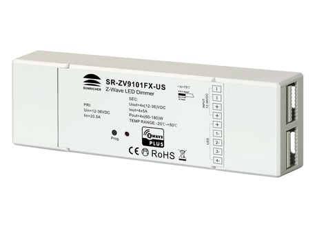
Product Picture


2 - Saving load state before power failure
Saving load state before power failureSize: 1 byte
Default: 0
Minimum: 0
Maximum: 0
Possible values
| From | To | Desription |
|---|---|---|
| 0 | 0 | shutoff load |
| 1 | 1 | turn on load |
| 2 | 2 | save load state before power failure |
3 - Enable/disable to send the basic report
Enable/disable to send the basic report to the Lifeline when the load state changed (When value set as 1, re-power on the dimmer, it will send Basic report automatically)Size: 1 byte
Default: 1
Minimum: 0
Maximum: 0
Possible values
| From | To | Desription |
|---|---|---|
| 0 | 0 | Disable to send Basic report |
| 1 | 1 | Enable to send Basic report |
4 - Select the type of the light band
Select the type of the light bandSize: 1 byte
Default: 2
Minimum: 0
Maximum: 0
Possible values
| From | To | Desription |
|---|---|---|
| 0 | 0 | single color light band, 4 channels PWM output to drive 4 channels single color light band |
| 1 | 1 | CCT light band, 2 channels PWM output, R(B) controls warm white, G(W) controls cool white |
| 2 | 2 | RGBW light band, 4 channels PWM output to drive RGBW light band |
5 - Choose a cool light stage mode
receiving Command Class Switch Color, or switching light band type, it recovers to normal lighting mode.) Remarks: When parameter number 4 is set as single color light band, the valid values of this parameter are 0~2.Size: 1 byte
Default: 0
Minimum: 0
Maximum: 0
Possible values
| From | To | Desription |
|---|---|---|
| 0 | 0 | inactive of light stage mode |
| 1 | 1 | fade in and fade out mode, colors set by parameter 8 |
| 2 | 2 | flash mode, colors set by parameter 8 |
| 3 | 3 | rainbow mode, system fixed changing effect |
| 4 | 4 | fade in and fade out mode, color changes randomly |
| 5 | 5 | flash mode, color changes randomly |
| 6 | 6 | rainbow mode, color changes randomly |
| 7 | 7 | random mode, the colors switch randomly |
6 - Speed of stage mode
Speed of stage modeSize: 1 byte
Default: 243
Minimum: 0
Maximum: 0
Possible values
| From | To | Desription |
|---|---|---|
| 0 | 255 | 0 is the slowest, 255(0xFF) is the fastest |
7 - Execution times of stage mode
Execution times of stage modeSize: 1 byte
Default: 0
Minimum: 0
Maximum: 0
Possible values
| From | To | Desription |
|---|---|---|
| 0 | 0 | unlimited times |
| 1 | 255 | 1~0xFF, execution times 1~255 |
8 - The hue of stage mode
The hue is only valid for fade in and fade out mode, flash modeSize: 1 byte
Default: 0
Minimum: 0
Maximum: 0
Possible values
| From | To | Desription |
|---|---|---|
| 0 | 255 | 0~0xFF value of hue,only valid for fade in and fade out mode, flash mode |
9 - Enable/disable external switch to be added to and removed from a network
Enable/disable external switch to be added to and removed from a network (when enables this function, triple press the external switch within 1.5 seconds to be added to or removed from a network)Size: 1 byte
Default: 0
Minimum: 0
Maximum: 0
Possible values
| From | To | Desription |
|---|---|---|
| 0 | 0 | disable |
| 1 | 1 | enable |
1. Set primary controller/gateway into inclusion mode (Please refer to your primary controllers manual on how to turn your controller into inclusion). 2. Power on the LED dimmer, make sure the LED dimmer does not belong to any Z-Wave network (please refer to the part “How to check whether the LED dimmer included to a network” of this manual). 1) When the connected LED light flashes quickly for 6 seconds, it means the LED dimmer does not belong to any network. Triple press the “Inclusion/Exclusion” button, it will be set into inclusion mode automatically, and waiting to be included. 2) When the connected LED light is under solid on status, it means the LED dimmer has already been included into a network. First you have to set the LED dimmer into exclusion mode, once excluded, it will be set into inclusion mode automatically, and waiting to be included. The connected LED light stays solid on 3s to indicate successful inclusion.
There are two exclusion methods: Method 1: Exclusion from the primary controller/gateway as follows: 1. Set the primary controller/gateway into exclusion mode (Please refer to your primary controllers manual on how to set your controller into exclusion). 2. Triple press the “inclusion/exclusion” button, the LED dimmer will be set to exclusion mode, the connected LED light will flash quickly for 6 seconds, and waiting to be excluded, then LED light stays solid on 3s to indicate successful exclusion. There are 3 methods for the LED dimmer to quit “exclusion mode”. Once the LED dimmer quits “exclusion mode”, the LED light will stop the fast flash status. 1. Automatically quits after successful exclusion. 2. Quits after 10 seconds timeout. 3. Power off and power on the LED dimmer. (Note: When the LED dimmer already included to a network, triple press “inclusion/exclusion” button, the LED dimmer will be set into exclusion mode and quit exclusion mode alternatively.) Method 2: Factory reset the LED dimmer will force the LED dimmer to be excluded from a network. (please refer to the part “Factory Reset” of this manual) Note: Factory reset is not recommended for exclusion, please use this procedure only if the primary controller/gateway is missing or otherwise inoperable.
Press and hold down “inclusion/exclusion” button for over 10 seconds, connected LED light stays solid on 3s to indicate successful factory reset, release “inclusion/exclusion” button, all 4 PWM outputs will restore to 50% brightness. Note: Factory reset is not recommended for exclusion, please use this procedure only if the primary controller/gateway is missing or otherwise inoperable.
| Type | Value(s) |
|---|
| Group | Type |
|---|---|
| System | (Refer to parameters): State idle |