Axis Communications
PIR Motion Sensor
T8341-JP
Notification Sensor
HW: 1 FW: 1.01:00.05
SD3502
6.71.01
0x0364 (868)
0x0002 (2)
0x0001 (1)
ZC10-18015970
2018-01-22 04:33:20.140482
N/A
Enhanced 232 Slave
Reporting Sleeping Slave
Yes
AXIS T8341 PIR Motion Sensor is a wireless sensor which provides motion detection both day and night.
AXIS T8341 PIR Motion Sensor is a wireless sensor which provides motion detection both day and night. With its support for wireless input/output connectivity, the PIR motion sensor can communicate wirelessly with AXIS M5065 PTZ Network camera or other connected Z-Wave Plus® controllers, creating a small security solution with less cabling. Thanks to its integrated wireless I/O connectivity, AXIS T8341 enables flexible installation as the sensor can easily be moved and adapted to your needs.
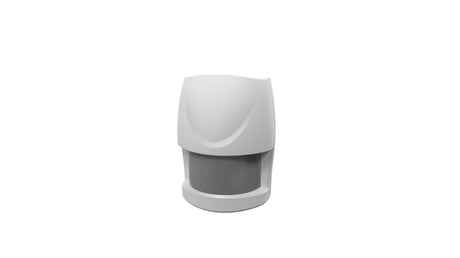
Product Picture


1 - Basic Set Level
When Basic Set Command is sent where contains a value, the receiver will take it for consideration; for instance, if a lamp module is received the Basic Set command of which value is decisive as to how bright of dim level of lamp module shall be.Size: 1 byte
Default: 99
Minimum: 0
Maximum: 0
Possible values
| From | To | Desription |
|---|---|---|
| 1 | 99 | ON (Binary Switch Device)/Dim Level (Multilevel Switch Device) |
3 - Sensitivity Level
In order to provide a best efficiency of the detector, it is recommended to test the detector with movements from a farthest end of the coverage area at first time of use. If movements cannot be detected sensitively, simply adjust the sensitivity level with Configuration Parameter #3. This parameter can be configured with the value of 1 through 10, where 1 means low sensitivity and 10 means highest sensitivity.Size: 1 byte
Default: 6
Minimum: 0
Maximum: 0
Possible values
| From | To | Desription |
|---|---|---|
| 1 | 10 | Sensitivity Level |
4 - Re-trigger Interval Setting
The Configuration parameter that can be used to adjust the interval of being re-triggered after the detector has been triggered as Configuration Parameter #4. No response will be made during this interval if a movement is presented. The time interval can be set between 5 secs to 3600 secs.Size: 2 bytes
Default: 180
Minimum: 0
Maximum: 0
Possible values
| From | To | Desription |
|---|---|---|
| 5 | 3600 | Re-trigger Interval Setting |
5 - Lux Level
The user can set a detecting percentage of lux level which determines when the light sensor will be activated. If percentage of lux level of ambient illumination falls below this percentage, and a person moves across or within the protected area, the detector will emit Z-Wave ON Command (i.e. Basic Set Command (Value = Basic Set Level)) to controller and activate connected modules and lighting. Percentage can be set between 1% to 100%.Size: 1 byte
Default: 20
Minimum: 0
Maximum: 0
Possible values
| From | To | Desription |
|---|---|---|
| 1 | 100 | Lux Level |
6 - On-Off Duration
The function of on-off duration setting will be useful if the detector is connected with a module or lighting. The duration determines how long the module/lighting should stay ON. For instance, Lamp Module turns off 100 secs after it has been turned on. This parameter can be configured with the value of 5 through 3600, where 5 means 5 second delay and 3600 means 3600 seconds of delay.Size: 2 bytes
Default: 15
Minimum: 0
Maximum: 0
Possible values
| From | To | Desription |
|---|---|---|
| 5 | 3600 | On-Off Duration |
Auto inclusion The motion sensor supports the auto inclusion feature where it will automatically enter Inclusion mode when first powered up. This will also apply when powered up after a factory reset. 1. Use a screwdriver to detach the rear cover. 2. Put the AXIS M6505 camera (Z-Wave controller) into inclusion mode. 3. Insert 1 CR123 3V batteries into the battery compartment with the correct polarity. The LED on the device should turn ON 4. The inclusion process should be completed when the LED stops blinking 5. Perform test before you refit the rear cover. Manual inclusion You can also choose to manually add the Z-Wave device to a control device. Please follow the steps described below. Note For best results, exclude the device before starting the inclusion process. For more details see the installation guide 1. Press the tamper switch 3 times within 1.5 seconds to put the unit into learning (inclusion/exclusion) mode. 2. The inclusion process should be completed when the LED stops blinking 3. Perform a test before you refit the cover.
Manual exclusion Note For more details see the installation guide 1. Detach the battery cover. 2. Press the tamper switch 3 times within 1.5 seconds to put the unit into learning (inclusion/exclusion) mode. 3. The exclusion process should be completed when the LED stops blinking 4. Refit the battery cover.
Wakeup Command Class After it has been included into a Z-Wave network, the detector will go to sleep but will send a Wakeup Notification Command periodically at preset period to the controller. The Motion detector will stay awake for 10 seconds at least and then go back to sleep to conserve battery life. The time interval between Wakeup Notification Commands can be set in the Wakeup Command Class based on the range values below: Minimum Wake Up Interval 600s (10 minutes) Maximum Wake Up Interval 86400s (1 day) Default Wake Up Interval 14400s (4 hours) Wake Up Interval Step Seconds 600s (10 minutes)
Factory Reset (This procedure should only be used when the controller is inoperable.) 1. Press the tamper switch 3 times within 1.5 seconds to put the unit into exclusion mode. 2. Within 1 second of step 1, press the tamper switch again and hold until LED is off (about 5 seconds). 3. Node ID is excluded. The device reverts to 2-second on, 2-second off factory default state and will be in auto-inclusion mode for 4 minutes.
The user can set a detecting percentage of lux level which determines when the light sensor will be activated. If percentage of lux level of ambient illumination falls below this percentage, and a person moves across or within the protected area, the detector will emit Z-Wave ON Command (i.e. Basic Set Command (Value = Basic Set Level)) to controller and activate connected modules and lighting. Percentage can be set between 1% to 100%.
| Type | Value(s) |
|---|
| Group | Type |
|---|---|
| Home Security | (Refer to parameters): State idle |