SE Devices
Standalone Mosfet Dimmer
AMD
Light Dimmer Switch
HW: 30 FW: 3.00:03.00
ZM5202
6.71.01
0x024F (591)
0x0003 (3)
0x1012 (4114)
ZC10-18046085
2018-02-22 21:39:31.374029
N/A
Enhanced 232 Slave
Always On Slave
Standalone Mosfet Dimmer (300W) for concealed in-wall monunting
The Standalone Mosfet Dimmer is a mosfet dimmer for concealed in-wall mounting. The device is exclusively Z-Wave controllable, which can handle dimmable loads up to 300W. The dimmer can operate in both Leading and Tailing Edge mode, which makes it capable of controlling most dimmable Lights on the market. All dimmer properties are configurable, making it possible to accurately customize the dimmer to the properies of the controlled Light Fixtures. The device supports power measurement, reporting both instant and accumulated power consumption over time.
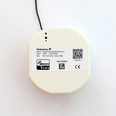
Product Picture


1 - Hardware Combination Identifier
READ-ONLY: Identifier which uniquely identifies the SE Devices hardware combination. Always return value 18 (0x12) for this device.Size: 1 byte
Default: 18
Minimum: 0
Maximum: 0
Possible values
| From | To | Desription |
|---|---|---|
| 18 | 18 | Hardware Combination Identifier |
10 - Dimming Speed
Defines the "fade" time when setting a dim level from a controller. Fade time is defined as the time it takes to dim from MIN level to MAX level, which means an increase of 10% in light level takes 1/10th of the configured time. The value defines the dim time in 1/100'th of a second, which means a value of 200 means the Dimming Speed is 2.0 seconds from MIN to MAX. Max time is 327.67 seconds (almost 5 and a half minute). Values below 30 (0.3 seconds) are ignored¸ and values below 100 (1 second) are discouraged.Size: 2 bytes
Default: 300
Minimum: 0
Maximum: 0
Possible values
| From | To | Desription |
|---|---|---|
| 30 | 32767 | Dimming Speed from MIN to MAX |
11 - Dimmer Mode
Defines if Dimmer should operate in Leading or Tailing Edge mode. Most Lights work quite OK in the default Leading Edge mode, but this mode also usually cause some noise from the dimmer unit. During installation it is therefore recommended to try TE mode, and use this if the Light operates properly. Tailing Edge mode is known to cause instability in some LED type Lights! 0 - Leading Edge Mode (LE) 1 - Leading Edge Mode (TE)Size: 1 byte
Default: 0
Minimum: 0
Maximum: 0
Possible values
| From | To | Desription |
|---|---|---|
| 0 | 1 | Leading or Tailing Edge Mode |
12 - Maximum Level
The Maximum Light level of the dimmer. Typically there is no visible difference when the dimming level reaches a point in the range 75 - 90, and the installer should set this value to the lowest value where no change is visible. The default value of 90 is usually OK.Size: 1 byte
Default: 90
Minimum: 0
Maximum: 0
Possible values
| From | To | Desription |
|---|---|---|
| 1 | 99 | Maximum Dimmer Level |
13 - Minimum Level
The Minimum Light Level of the dimmer. This should be adjusted so the controlled Light is still ON and stable. Remember that LED type lights may work if dimmed down to a low value, but may not start if the light is turned OFF and ON again.Size: 1 byte
Default: 15
Minimum: 0
Maximum: 0
Possible values
| From | To | Desription |
|---|---|---|
| 1 | 99 | Minimum Dimmer Level |
16 - Back Unit Type
READ-ONLY: Identifies the local functionality of devices in the SE Devices product range. Always return value 2 for Mosfet Dimmer functionality.Size: 1 byte
Default: 2
Minimum: 0
Maximum: 0
Possible values
| From | To | Desription |
|---|---|---|
| 2 | 2 | Local Functionality Identifier |
44 - Cold Start Minimum Level
Sets the minimum level the Dimmer should go to when the light is switched ON. If the last dimmer value is lower than this setting, the dimmer will first go to the configured Cold Start level, before returning to the target level. This is typically used for LED lamps which does not switch ON correctly when the dimming level is at the Minimum.Size: 1 byte
Default: 20
Minimum: 0
Maximum: 0
Possible values
| From | To | Desription |
|---|---|---|
| 1 | 99 | Minimum ON level on Cold Start |
To add the device to a Z-Wave network, the Z-Wave Controller must first be set into Add (Learn) mode. Then use a paperclip or a small pointy tool to push and hold the button in the button hole for approximately a second. The device LED will blink twice to indicate that it sends information to the Controller.
To remove the device from a Z-Wave network, the Z-Wave Controller must first be set into Remove mode. Then use a paperclip or a small pointy tool to push and hold the button in the button hole for approximately a second. The device LED will blink twice to indicate that it sends information to the Controller.
WARNING! Executing a Factory Reset on a device may make it stop working as wanted, and will disable remote control of the device. The device will have to be re-added to the Z-Wave network and reconfigured afterwards, to regain the previous operation of the device. Please DO NOT execute this procedure unless it is absolutely necessary. Push and Hold the Add/Remove button for about 15 seconds – until the LED indicator turns OFF. Then release the button. The device is now Factory Reset, and removed from the Z-Wave network. The button is located about 10 mm down in the middle of the three holes on the front. A thin tool (a very small screwdriver, a toothpick, a paper clip or similar) is needed to access the button.
Universal dimmer supporting both Leading and Tailing Edge dimming. All parameters of the dimmers are customizable via configuration, to fit most types of Light Fixtures.
| Type | Value(s) |
|---|
| Sensor type |
|---|
| Power |
| Voltage |
| Current |
| Meter type |
|---|
| Electric Meter Consumption |