Aeotec
TriSensor
ZWA005-A
Notification Sensor
HW: 17 FW: 2.08:01.32
ZM5101
6.71.01
0x0371 (881)
0x0102 (258)
0x0005 (5)
ZC10-18056128
2018-05-01 05:47:45.780731
N/A
Enhanced 232 Slave
Reporting Sleeping Slave
Yes
Aeotec TriSensor has motion detector, ambient temperature and ambient light sensor in one which based on Z-Wave™Plus technology.
Aeotec TriSensor is a universal Z-Wave Plus compatible product, consists of temperature, lighting and motion sensors, powered by a CR123A battery. It can be included and operated in any Z-Wave network with other Z-Wave certified devices from other manufacturers and/or other applications. By the built-in motion sensor, an alam will be sent to the gateway when the motion sensor is triggered.
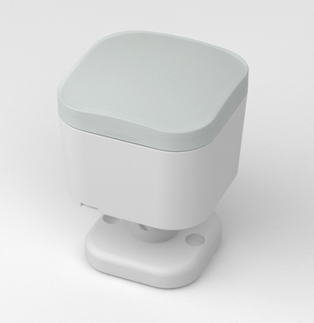
Product Picture


1 - Motion Retrigger Time
This parameter is configured the delay time before PIR sensor can be triggered again to reset motion timeout counter. Value = 0 will disable PIR sensor from triggering until motion timeout has finished.Size: 2 bytes
Default: 30
Minimum: 0
Maximum: 0
Possible values
| From | To | Desription |
|---|---|---|
| 0 | 32767 | Value = 0 will disable PIR sensor from triggering until motion timeout has finished. |
2 - Motion Clear Time
This parameter is configured the time to clear motion event after a motion event detected. Time to motion clear, the device will send a clear event report to controller and send BASIC_SET = 0x00 to nodes associated in group 2. Unit: Second.Size: 2 bytes
Default: 240
Minimum: 0
Maximum: 0
Possible values
| From | To | Desription |
|---|---|---|
| 1 | 32767 | Unit: Second. |
3 - Motion Sensitivity
This parameter is configured the sensitivity that motion detect. 0 – PIR sensor disabled. 1 – Lowest sensitivity. 11– Highest sensitivitySize: 1 byte
Default: 11
Minimum: 0
Maximum: 0
Possible values
| From | To | Desription |
|---|---|---|
| 0 | 11 | 0 – PIR sensor disabled. 1 – Lowest sensitivity. 11– Highest sensitivity |
4 - Binary Sensor Report Enable
‘0’ –Disable sensor binary report when motion event is detected or cleared. ‘1’ –Enable sensor binary report when motion event is detected or cleared.Size: 1 byte
Default: 0
Minimum: 0
Maximum: 0
Possible values
| From | To | Desription |
|---|---|---|
| 0 | 1 | ‘0’ –Disable sensor binary report when motion event is detected or cleared. ‘1’ –Enable sensor binary report when motion event is detected or cleared. |
5 - Disable BASIC_SET to Associated nodes
This parameter is configured the enabled or disabled send BASIC_SET command to nodes that associated in group 2 and group 3. 0 – Disabled All Group Basic Set Command 1 – Enabled Group 2 Basic Set Command, Group 3 Basic Set Command is disabled. 2 – Enabled Group 3 Basic Set Command, Group 2 Basic Set Command is disabled. 3 – Enabled Group 2 and Group 3 Basic Set Command.Size: 1 byte
Default: 3
Minimum: 0
Maximum: 0
Possible values
| From | To | Desription |
|---|---|---|
| 0 | 3 | 0 – Disabled All Group Basic Set Command 1 – Enabled Group 2 Basic Set Command, Group 3 Basic Set Command is disabled. 2 – Enabled Group 3 Basic Set Command, Group 2 Basic Set Command is disabled. 3 – Enabled Group 2 and Group 3 Basic Set Command. |
6 - Basic Set Value Settings for Group 2
‘0’ – Send BASIC_SET = 0xFF to devices associated in Group 2 when motion event is triggered, send BASIC_SET = 0x00 to devices associated in group 2 when motion event is cleared. ‘1’– Send BASIC_SET = 0x00 to devices associated in Group 2 when motion event is triggered, send BASIC_SET = 0xFF to devices associated in group 2 when motion event is cleared. ‘2’ – Send BASIC_SET = 0xFF to devices associated in Group 2 when motion event is triggered. ‘3’ – Send BASIC_SET = 0x00 to devices associated in Group 2 when motion event is triggered. ‘4’ – Send BASIC_SET = 0x00 to devices associated in Group 2 when motion event is cleared. ‘5’ – Send BASIC_SET = 0xFF to devices associated in Group 2 when motion event is cleared.Size: 1 byte
Default: 0
Minimum: 0
Maximum: 0
Possible values
| From | To | Desription |
|---|---|---|
| 0 | 5 | ‘1’– Send BASIC_SET = 0x00 to devices associated in Group 2 when motion event is triggered, send BASIC_SET = 0xFF to devices associated in group 2 when motion event is cleared. ‘2’ – Send BASIC_SET = 0xFF to devices associated in Group 2 when motion event is triggered. ‘3’ – Send BASIC_SET = 0x00 to devices associated in Group 2 when motion event is triggered. ‘4’ – Send BASIC_SET = 0x00 to devices associated in Group 2 when motion event is cleared. ‘5’ – Send BASIC_SET = 0xFF to devices associated in Group 2 when motion event is cleared. |
7 - Temperature Alarm Value
This parameter is configured the threshold value that alarm level for temperature. When the current ambient temperature value is larger than this configuration value, device will send a BASIC_SET = 0xFF to nodes associated in group 3. If current temperature value is less than this value, device will send a BASIC_SET = 0x00 to nodes associated in group 3. Value = [Value] × 0.1(Celsius / Fahrenheit)Size: 2 bytes
Default: 750
Minimum: 0
Maximum: 0
Possible values
| From | To | Desription |
|---|---|---|
| -400 | 1185 | Value = [Value] × 0.1(Celsius / Fahrenheit) |
10 - Led Indicate Disable
This parameter is configured the Led light on disable or enable. ‘1’ – Enable Led Blink when device detects a motion event. ‘0’ – Disable Led Blink. This configuration is not affect inclusion, exclusion and reset.Size: 1 byte
Default: 1
Minimum: 0
Maximum: 0
Possible values
| From | To | Desription |
|---|---|---|
| 0 | 1 | ‘1’ – Enable Led Blink when device detects a motion event. ‘0’ – Disable Led Blink. This configuration is not affect inclusion, exclusion and reset. |
11 - Led Color For Motion Event Report
‘0’ – Disable. ‘1’ – Red. ‘2’ – Green. ‘3’ – Blue. ‘4’ – Yellow. ‘5’ – Pink. ‘6’ – Cyan. ‘7’ – Purple. ‘8’ – Orange.Size: 1 byte
Default: 2
Minimum: 0
Maximum: 0
Possible values
| From | To | Desription |
|---|---|---|
| 0 | 8 | ‘0’ – Disable. ‘1’ – Red. ‘2’ – Green. ‘3’ – Blue. ‘4’ – Yellow. ‘5’ – Pink. ‘6’ – Cyan. ‘7’ – Purple. ‘8’ – Orange. |
12 - Led Color For Temperature Sensor Report
‘0’ – Disable. ‘1’ – Red. ‘2’ –Green. ‘3’ – Blue. ‘4’ – Yellow. ‘5’ – Pink. ‘6’ – Cyan. ‘7’ – Purple. ‘8’ – Orange.Size: 1 byte
Default: 0
Minimum: 0
Maximum: 0
Possible values
| From | To | Desription |
|---|---|---|
| 0 | 8 | ‘0’ – Disable. ‘1’ – Red. ‘2’ –Green. ‘3’ – Blue. ‘4’ – Yellow. ‘5’ – Pink. ‘6’ – Cyan. ‘7’ – Purple. ‘8’ – Orange. |
13 - Led Color For Light Sensor Report
‘0’ – Disable. ‘1’ – Red. ‘2’ –Green. ‘3’ – Blue. ‘4’ – Yellow. ‘5’ – Pink. ‘6’ – Cyan. ‘7’ – Purple. ‘8’ – OrangeSize: 1 byte
Default: 0
Minimum: 0
Maximum: 0
Possible values
| From | To | Desription |
|---|---|---|
| 0 | 8 | ‘0’ – Disable. ‘1’ – Red. ‘2’ –Green. ‘3’ – Blue. ‘4’ – Yellow. ‘5’ – Pink. ‘6’ – Cyan. ‘7’ – Purple. ‘8’ – Orange |
14 - Led Color For Battery Report
‘0’ – Disable. ‘1’ – Red. ‘2’ –Green. ‘3’ – Blue. ‘4’ – Yellow. ‘5’ – Pink. ‘6’ – Cyan. ‘7’ – Purple. ‘8’ – Orange.Size: 1 byte
Default: 0
Minimum: 0
Maximum: 0
Possible values
| From | To | Desription |
|---|---|---|
| 0 | 8 | ‘0’ – Disable. ‘1’ – Red. ‘2’ –Green. ‘3’ – Blue. ‘4’ – Yellow. ‘5’ – Pink. ‘6’ – Cyan. ‘7’ – Purple. ‘8’ – Orange. |
15 - Led Color For Wakeup Notification Report
‘0’ – Disable. ‘1’ – Red. ‘2’ –Green. ‘3’ – Blue. ‘4’ – Yellow. ‘5’ – Pink. ‘6’ – Cyan. ‘7’ – Purple. ‘8’ – Orange.Size: 1 byte
Default: 0
Minimum: 0
Maximum: 0
Possible values
| From | To | Desription |
|---|---|---|
| 0 | 8 | ‘0’ – Disable. ‘1’ – Red. ‘2’ –Green. ‘3’ – Blue. ‘4’ – Yellow. ‘5’ – Pink. ‘6’ – Cyan. ‘7’ – Purple. ‘8’ – Orange. |
20 - Temperature Scale Setting
Configure temperature sensor scale type, Temperature to report in Celsius or Fahrenheit. 0 – Celsius (C). 1 – Fahrenheit (F).Size: 1 byte
Default: 1
Minimum: 0
Maximum: 0
Possible values
| From | To | Desription |
|---|---|---|
| 0 | 1 | 0 – Celsius (C). 1 – Fahrenheit (F). |
21 - Temperature Threshold Value to Report
Change threshold value for change in temperature to induce an automatic report for temperature sensor. Scale is identical setting in Parameter No.20. Setting of value 20 can be a change of -2.0 or +2.0 (C or F depending on Parameter No.20) to induce automatic report or setting a value of 2 will be a change of 0.2(C or F).Size: 2 bytes
Default: 20
Minimum: 0
Maximum: 0
Possible values
| From | To | Desription |
|---|---|---|
| 0 | 250 | Temperature Threshold Value |
22 - Light intensity Threshold Value to Report
Change threshold value for change in light sensor to induce an automatic report for temperature sensor. Scale: Lux.Size: 2 bytes
Default: 100
Minimum: 0
Maximum: 0
Possible values
| From | To | Desription |
|---|---|---|
| 0 | 10000 | Scale: Lux. |
23 - Temperature Sensor Report Interval
This parameter is configured the time interval for temperature sensor report. This value is larger, the battery life is longer. And the temperature value changed is not obvious. Unit: Second.Size: 2 bytes
Default: 3600
Minimum: 0
Maximum: 0
Possible values
| From | To | Desription |
|---|---|---|
| 1 | 32767 | Unit: Second. |
24 - Light Sensor Report Interval
This parameter is configured the time interval for light sensor report. This value is larger, the battery life is longer. And the light intensity changed is not obvious. Unit: Second.Size: 2 bytes
Default: 3600
Minimum: 0
Maximum: 0
Possible values
| From | To | Desription |
|---|---|---|
| 1 | 32767 | Unit: Second. |
30 - Temperature Offset Value
The current measuring temperature value can be add and minus a value by this setting. The scale can be decided by Parameter Number 20. Temperature Offset Value = [Value] * 0.1(Celsius / Fahrenheit)Size: 2 bytes
Default: 0
Minimum: 0
Maximum: 0
Possible values
| From | To | Desription |
|---|---|---|
| -200 | 200 | Temperature Offset Value = [Value] * 0.1(Celsius / Fahrenheit) |
31 - Light Intensity Offset Value
The current measuring light intensity value can be add and minus a value by this setting.Size: 2 bytes
Default: 0
Minimum: 0
Maximum: 0
Possible values
| From | To | Desription |
|---|---|---|
| -1000 | 1000 | Scale: Lux. |
100 - Light Sensor Calibrated Coefficient
This configuration defines the calibrated scale for ambient light intensity. Because the method and position that the sensor mounted and the cover of sensor will bring measurement error, user can get more real light intensity by this parameter setting. User should run the steps as blows for calibrating 1) Set this parameter value to default (Assumes the sensor has been added in a Z- Wave Network). 2) Place a digital luxmeter close to sensor and keep the same direction, monitor the light intensity value (Vm) which report to controller and record it. The same time user should record the value (Vs) of luxmeter. 3) The scale calibration formula: k = Vm / Vs. 4) The value of k is then multiplied by 1024 and rounded to the nearest whole number. 5) Set the value getting in 5) to this parameter, calibrate finished. For example, Vm = 300, Vs = 2600, then k = 2600 / 300 = 8.6667 k = 8.6667 * 1024 = 8874.7 ≈ 8875 The parameter should be set to 8875.Size: 2 bytes
Default: 1024
Minimum: 0
Maximum: 0
Possible values
| From | To | Desription |
|---|---|---|
| 1 | 32767 | Scale: Lux. |
Press once TriSensor’s Action Button. If it is the first installation, the yellow LED will keep solid until whole network processing is complete. If successful, the LED will flash white -> green -> white -> green, after 2 seconds finished. If failed, the yellow LED lasts for 30 seconds, then the green LED flashes once. If it is the S2 encryption network, please enter the first 5 digits of DSK.
Press once TriSensor’s Action Button, the Purple LED will keep solid until whole network processing is complete. If the exclusion is successful, the LED will flash white -> green - >white -> green and then LED will pulse a blue. If failed, the yellow LED lasts for 30 seconds, then the green LED flashes once.
Press and hold the button at least 2s until Red Led is on and then release the button,device will send wakeup notification to controller if device is in a Z-Wave network.
1. Power up the device. 2. Press and hold the button for 15s until Red Led is blinking,then release the button. Note: Please use this procedure only when the network primary controller is missing or otherwise inoperable.
| Type | Value(s) |
|---|
| Group | Type |
|---|---|
| Home Security | (Refer to parameters): State idle |
| Sensor type |
|---|
| Air Temperature |
| General Purpose |
| Illuminance |