HomeSeer
Z-Wave RGB Fan Controller
HS-FC200+
Fan Switch
HW: 255 FW: 50.01
ZM5101
6.81.00
0x000C (12)
0x0203 (515)
0x0001 (1)
ZC10-18066137
2018-06-05 21:27:55.803774
N/A
Enhanced 232 Slave
Always On Slave
HS-FC200+ is a Z-Wave controllable wired fan controller for use with 3-speed or 4-speed ceiling fans.
HS-FC200+ is a Z-Wave controllable wired fan controller for use with 3-speed or 4-speed ceiling fans. It has a vertical row of LED’s that indicate the fan speed level. • Works with 3-speed or 4-speed fans only • 4 segment LED dim level indicator • Remotely or manually turns ON or OFF, or fan speed level • Fits standard wall plates (wall plate not included) • Works with any certified gateway supporting Z-Wave
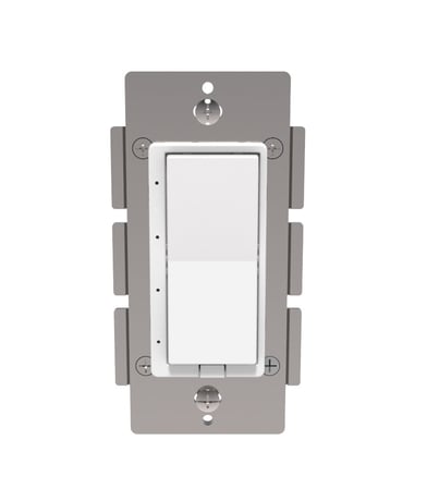
Product Picture


3 - Nightlight Mode
Nightlight Mode, sets bottom LED operation (in normal mode). 0= bottom LED on if load is off. 1= off if load is offSize: 1 byte
Default: 1
Minimum: 0
Maximum: 1
Possible values
| From | To | Desription |
|---|---|---|
| 0 | 1 | 0= bottom LED on if load is off. 1= off if load is off |
4 - Sets paddles load orientation
Sets whether the top or the bottom paddle turns the load ONSize: 1 byte
Default: 0
Minimum: 0
Maximum: 1
Possible values
| From | To | Desription |
|---|---|---|
| 0 | 1 | 0 = Top On 1 = Bottom On |
5 - Sets fan type
Sets the supported fan type, 3 or 4 speedSize: 1 byte
Default: 0
Minimum: 0
Maximum: 1
Possible values
| From | To | Desription |
|---|---|---|
| 0 | 1 | 0=3 speed fan 1=4 speed fan |
13 - Sets LED indicator mode of operation
0=Fan Controller LED acts like a Fan Controller 1=Fan Controller LED acts like a status indicator (LEDs should display the current fan speed level when you tap the paddle)Size: 1 byte
Default: 0
Minimum: 0
Maximum: 1
Possible values
| From | To | Desription |
|---|---|---|
| 0 | 1 | 0=Fan Controller LED acts like a Fan Controller 1=Fan Controller LED acts like a status indicator (LEDs should display the current fan speed level when you tap the paddle) |
14 - Sets the Normal mode LED color
Sets the default LED color when the Fan Controller is NOT in status mode. All LEDS will use this color in this mode. The color values are: 0=White 1=Red 2=Green 3=Blue 4=Magenta 5=Yellow 6=CyanSize: 1 byte
Default: 0
Minimum: 0
Maximum: 6
Possible values
| From | To | Desription |
|---|---|---|
| 0 | 6 | Sets the default LED color when the Fan Controller is NOT in status mode. All LEDS will use this color in this mode. The color values are: 0=White 1=Red 2=Green 3=Blue 4=Magenta 5=Yellow 6=Cyan |
21 - Sets status mode LED 1 bottom color
Sets status mode LED 1 bottom color 0=Off 1=Red 2=Green 3=Blue 4=Magenta 5=Yellow 6=Cyan 7=WhiteSize: 1 byte
Default: 0
Minimum: 0
Maximum: 7
Possible values
| From | To | Desription |
|---|---|---|
| 0 | 7 | Sets status mode LED 1 bottom color 0=Off 1=Red 2=Green 3=Blue 4=Magenta 5=Yellow 6=Cyan 7=White |
22 - Sets status mode LED 2 color
Sets status mode LED 2 color 0=Off 1=Red 2=Green 3=Blue 4=Magenta 5=Yellow 6=Cyan 7=WhiteSize: 1 byte
Default: 0
Minimum: 0
Maximum: 7
Possible values
| From | To | Desription |
|---|---|---|
| 0 | 7 | Sets status mode LED 2 color 0=Off 1=Red 2=Green 3=Blue 4=Magenta 5=Yellow 6=Cyan 7=White |
23 - Sets status mode LED 3 color
Sets status mode LED 3 color 0=Off 1=Red 2=Green 3=Blue 4=Magenta 5=Yellow 6=Cyan 7=WhiteSize: 1 byte
Default: 0
Minimum: 0
Maximum: 7
Possible values
| From | To | Desription |
|---|---|---|
| 0 | 7 | Sets status mode LED 3 color 0=Off 1=Red 2=Green 3=Blue 4=Magenta 5=Yellow 6=Cyan 7=White |
24 - Sets status mode LED 4 color
Sets status mode LED 4 color 0=Off 1=Red 2=Green 3=Blue 4=Magenta 5=Yellow 6=Cyan 7=WhiteSize: 1 byte
Default: 0
Minimum: 0
Maximum: 7
Possible values
| From | To | Desription |
|---|---|---|
| 0 | 7 | Sets status mode LED 4 color 0=Off 1=Red 2=Green 3=Blue 4=Magenta 5=Yellow 6=Cyan 7=White |
30 - Sets the Blink frequency for All LEDs in Status mode
Sets the Blink frequency for All LEDs in Status mode Possible values: 0-255 0= No blink, 1=100ms (100 ms off then 100ms on)Size: 1 byte
Default: 0
Minimum: 0
Maximum: 255
Possible values
| From | To | Desription |
|---|---|---|
| 0 | 255 | 0= No blink, 1=100ms (100 ms off then 100ms on) |
31 - Sets LEDs 1-4 to Blink in Status mode
Bitmask defines specific LEDs to enable for blinking. Note: this decimal value is derived from a hex code calculation based on the following: 0x01 = led 1 0x02 = led 2 0x04 = led 3 0x08 = led 4 0 = All LED's disabled 1 = LED 1 2 = LED 2 3 = LED 1 and 2 4 = LED 3 5 = LED 3 and 1 6 = LED 3 and 2 7 = LED 3 and 2 and 1 8 = LED 4 9 = LED 4 and 1 10 = LED 4 and 2 11 = LED 4 and 2 and 1 12 = LED 4 and 3 13 = LED 4 and 3 and 1 14 = LED 4 and 3 and 2 15 = LED 4 and 3 and 2 and 1Size: 1 byte
Default: 0
Minimum: 0
Maximum: 15
Possible values
| From | To | Desription |
|---|---|---|
| 0 | 15 | 0 = All LEDs disabled 1 = LED 1 2 = LED 2 3 = LED 1 and 2 4 = LED 3 5 = LED 3 and 1 6 = LED 3 and 2 7 = LED 3 and 2 and 1 8 = LED 4 9 = LED 4 and 1 10 = LED 4 and 2 11 = LED 4 and 2 and 1 12 = LED 4 and 3 13 = LED 4 and 3 and 1 14 = LED 4 and 3 and 2 15 = LED 4 and 3 and 2 and 1 |
Inclusion: Add the device into your network by a Z-Wave certified controller. HS-FC200+ supports the latest S2 security offered by Z-Wave certified controllers. If your controller supports S2, please refer to the user guide of the controller for detailed instructions on adding devices to the network. You should be able to add HS-FC200+ into your network using the unique QR code or the DSK 5 digit pin located on the product or packaging. In addition, the device can be added or removed using the following 2-step procedure: 1. Put your Z-Wave controller into Inclusion mode. Consult your controller manual if you're unsure how to do this. 2. Tap the paddle of your new HomeSeer switch to begin the inclusion process. This will take a few moments to complete.
Exclusion: Remove the device from your network by a Z-Wave certified controller. HS-FC200+ supports the latest S2 security offered by Z-Wave certified controllers. If your controller supports S2, please refer to the user guide of the controller for detailed instructions on removing devices from the network. You should be able to remove HS-FC200+ into your network using the unique QR code or the DSK 5 digit pin located on the product or packaging. In addition, the device can be added or removed using the following 2-step procedure: 1. Put your Z-Wave controller into Exclusion mode. Consult your controller manual if you're unsure how to do this. 2. Tap the paddle of your new HomeSeer switch to begin the Exclusion process. This will take a few moments to complete.
To be used only in the event that the network primary controller is lost or otherwise inoperable. (1) Turn switch on by tapping the top of the paddle once. (2) Quickly ap top of the paddle 3 times. (3) Quickly tap bottom of paddle 3 times. (4) If the LED turns off then on again, switch is reset. If not, repeat manual rest.
Under S2 Security / SmartStart, it is mentioned that the, ""DSK can be found on the front metal yoke of the device.""
| Type | Value(s) |
|---|