RCS
REM50Z
REM50Z
Notification Sensor
HW: 1 FW: 6.61:01.00
ZM5202
6.61.00
0x0010 (16)
0x454D (17741)
0x3530 (13616)
ZC10-18076173
2018-06-30 01:08:02.226833
N/A
Routing Slave
Always On Slave
The REM50Z is a wall mountable sensor for remotely monitoring up to 4 temperatures and has a voltage detection circuit that can be used to monitor condensate pan fill level of an HVAC system.
The REM50Z (Remote Equipment Monitor) Quad Channel Remote Temperature Sensor is a wall mountable Z-Wave remote temperature sensor for use with all Z-Wave systems. This sensor is ideal for remotely monitoring up to 4 operating temperatures on HVAC systems: Supply, Return, and Refrigeration In/Out Line Temps. Additionally, the REM50 has a single channel contact closure / voltage detection circuit that can be used to monitor and report Condensate Pan fill level of the HVAC system. Features • Z-Wave 500 Series Radio • Supports Z-Wave Plus • Quad Temp Sensor Circuits: +/- 1 degree F, Range: -40F to 120F o Designed for 10k Thermistor temp sensors, not included • 1 Contact Closure / Voltage Detection Circuit o Designed to detect Float Switch closure, not included • 6 Status LEDs • Designed for interior use in mechanical room, attic or crawlspace • Compatible with RCS Z-Wave Thermostats • Compatible with all Z-Wave systems • Wall Mountable • Small, Thin, Lightweight • Grey, Paintable Dimensions • 5.10” X 2.25” X 0.9” Power • 16 – 28 VAC • 12 – 24 VDC
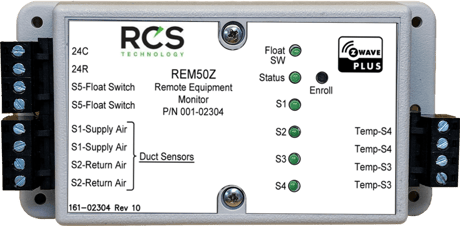
Product Picture


1 - RS1 Sensor Cal
Add or subtract an offset for the S1 temperature sensor.Size: 1 byte
Default: 0
Minimum: 0
Maximum: 0
Possible values
| From | To | Desription |
|---|---|---|
| -7 | 7 | Degrees |
3 - RS3 Sensor Cal
Add or subtract an offset for the S3 temperature sensor.Size: 1 byte
Default: 0
Minimum: 0
Maximum: 0
Possible values
| From | To | Desription |
|---|---|---|
| -7 | 7 | Degrees |
4 - RS4 Sensor Cal
Add or subtract an offset for the S4 temperature sensor.Size: 1 byte
Default: 0
Minimum: 0
Maximum: 0
Possible values
| From | To | Desription |
|---|---|---|
| -7 | 7 | Degrees |
5 - RS1 Lifeline Temperature Delta Autosend Threshold
How many degrees need to change to trigger a temperature report.Size: 1 byte
Default: 1
Minimum: 0
Maximum: 0
Possible values
| From | To | Desription |
|---|---|---|
| 1 | 20 | Degrees |
6 - RS2 Lifeline Temperature Delta Autosend Threshold
How many degrees need to change to trigger a temperature report.Size: 1 byte
Default: 1
Minimum: 0
Maximum: 0
Possible values
| From | To | Desription |
|---|---|---|
| 1 | 20 | Degrees |
7 - RS3 Lifeline Temperature Delta Autosend Threshold
How many degrees need to change to trigger a temperature report.Size: 1 byte
Default: 1
Minimum: 0
Maximum: 0
Possible values
| From | To | Desription |
|---|---|---|
| 1 | 20 | Degrees |
8 - RS4 Lifeline Temperature Delta Autosend Threshold
How many degrees need to change to trigger a temperature report.Size: 1 byte
Default: 1
Minimum: 0
Maximum: 0
Possible values
| From | To | Desription |
|---|---|---|
| 1 | 20 | Degrees |
9 - RS1 Lifeline Periodic Temperature Send Interval
How many minutes between periodic temperature reports.Size: 1 byte
Default: 120
Minimum: 0
Maximum: 0
Possible values
| From | To | Desription |
|---|---|---|
| 1 | 120 | Minutes |
10 - RS2 Lifeline Periodic Temperature Send Interval
How many minutes between periodic temperature reports.Size: 1 byte
Default: 120
Minimum: 0
Maximum: 0
Possible values
| From | To | Desription |
|---|---|---|
| 1 | 120 | Minutes |
11 - RS3 Lifeline Periodic Temperature Send Interval
How many minutes between periodic temperature reports.Size: 1 byte
Default: 120
Minimum: 0
Maximum: 0
Possible values
| From | To | Desription |
|---|---|---|
| 1 | 120 | Minutes |
12 - RS4 Lifeline Periodic Temperature Send Interval
How many minutes between periodic temperature reports.Size: 1 byte
Default: 120
Minimum: 0
Maximum: 0
Possible values
| From | To | Desription |
|---|---|---|
| 1 | 120 | Minutes |
13 - RS1 Group2 Temperature Delta Autosend Threshold
How many degrees need to change to trigger a temperature report to association group 2.Size: 1 byte
Default: 1
Minimum: 0
Maximum: 0
Possible values
| From | To | Desription |
|---|---|---|
| 1 | 5 | Degrees |
14 - RS2 Group3 Temperature Delta Autosend Threshold
How many degrees need to change to trigger a temperature report to association group 3.Size: 1 byte
Default: 1
Minimum: 0
Maximum: 0
Possible values
| From | To | Desription |
|---|---|---|
| 1 | 5 | Degrees |
15 - RS3 Group4 Temperature Delta Autosend Threshold
How many degrees need to change to trigger a temperature report to association group 4.Size: 1 byte
Default: 1
Minimum: 0
Maximum: 0
Possible values
| From | To | Desription |
|---|---|---|
| 1 | 5 | Degrees |
16 - RS4 Group5 Temperature Delta Autosend Threshold
How many degrees need to change to trigger a temperature report to association group 5.Size: 1 byte
Default: 1
Minimum: 0
Maximum: 0
Possible values
| From | To | Desription |
|---|---|---|
| 1 | 5 | Degrees |
17 - RS1 Group2 Periodic Temperature Send Interval
How many minutes between periodic temperature reports to association group 2.Size: 1 byte
Default: 0
Minimum: 0
Maximum: 0
Possible values
| From | To | Desription |
|---|---|---|
| 0 | 120 | Minutes |
18 - RS2 Group3 Periodic Temperature Send Interval
How many minutes between periodic temperature reports to association group 3.Size: 1 byte
Default: 0
Minimum: 0
Maximum: 0
Possible values
| From | To | Desription |
|---|---|---|
| 0 | 120 | Minutes |
19 - RS3 Group4 Periodic Temperature Send Interval
How many minutes between periodic temperature reports to association group 4.Size: 1 byte
Default: 0
Minimum: 0
Maximum: 0
Possible values
| From | To | Desription |
|---|---|---|
| 0 | 120 | Minutes |
20 - RS4 Group5 Periodic Temperature Send Interval
How many minutes between periodic temperature reports to association group 5.Size: 1 byte
Default: 0
Minimum: 0
Maximum: 0
Possible values
| From | To | Desription |
|---|---|---|
| 0 | 120 | Minutes |
21 - HVAC Thermistor Curve
Select the type of thermistor used.Size: 1 byte
Default: 0
Minimum: 0
Maximum: 0
Possible values
| From | To | Desription |
|---|---|---|
| -7 | 7 | Degrees |
| 0 | 1 | 0=10k Type 2, 1= 10k Type 3 |
22 - RS1 Time Constant
Filter Time constant. Larger number gives a slower temperature response.Size: 1 byte
Default: 10
Minimum: 0
Maximum: 0
Possible values
| From | To | Desription |
|---|---|---|
| 1 | 60 | Seconds |
23 - RS2 Time Constant
Filter Time constant. Larger number gives a slower temperature response.Size: 1 byte
Default: 10
Minimum: 0
Maximum: 0
Possible values
| From | To | Desription |
|---|---|---|
| 1 | 60 | Seconds |
24 - RS3 Time Constant
Filter Time constant. Larger number gives a slower temperature response.Size: 1 byte
Default: 10
Minimum: 0
Maximum: 0
Possible values
| From | To | Desription |
|---|---|---|
| 1 | 60 | Seconds |
25 - RS4 Time Constant
Filter Time constant. Larger number gives a slower temperature response.Size: 1 byte
Default: 10
Minimum: 0
Maximum: 0
Possible values
| From | To | Desription |
|---|---|---|
| 1 | 60 | Seconds |
Inclusion: Including the REM50Z into an Existing Network: 1. Set your primary controller to Include mode, to add the REM50Z as a node on your network (see your controller’s user manual for detailed instructions). 2. Press the Install button. The controller will indicate the device has been included into the network. Your controller will indicate the REM50Z was successfully added to its network (see your controller’s user manual for details). Inclusion and exclusion are always done at normal transmit power mode. If your controller supports NWI, then you can optionally set the primary to NWI include mode. Please note that NWI inclusion mode does not end when you have included a new node. This allows multiple nodes to be included without having to physically go back to the controller to initiate the next inclusion. Therefore you must manually terminate NWI inclusion mode at the controller when you have finished including any new nodes to the network. Since intermediate included nodes will assist the inclusion process by routing messages, we recommend that nodes close to the primary controller be installed first, proceeding out in consecutive rings from the controller. Note: Consult your controller’s user manual for details on removing a device from a Z-Wave network.
Exclusion: Removing the REM50Z from a Network: 1. Set your primary controller to Remove mode, to remove the REM50Z as a node on your network (see your controller’s user manual for detailed instructions). 2. Press the Install button. The controller will indicate the device has been removed from the network.
Factory Reset NOTE: A Factory Reset should only be performed if the network controller is missing or inoperable. To reset the REM50Z’s configurations and Z-Wave parameters to Factory Settings (Including association groups and scene configurations), and remove the REM50Z from any Z-Wave network: 1. Hold down the Install button for approximately 10 seconds 2. Release the install button (the REM50Z will reset all internal configuration including Z-Wave configurations). The unit will then reset. 3. When the Status LED begins to blink (un-enrolled) the unit has finished restoring configurations is running in normal mode. A Restore Defaults will be performed automatically when removed from a network.
| Type | Value(s) |
|---|
| Group | Type |
|---|---|
| Water Alarm | (Refer to parameters): State idle |
| Sensor type |
|---|
| Air Temperature |
| Voltage |