Eaton
Eatons Z-Wave Plus Wireless Receptacle
RFTR9605-T
On/Off Power Switch
HW: 0 FW: 2.00
ZM5101
6.71.03
0x001A (26)
0x5244 (21060)
0x0505 (1285)
ZC10-18096232
2018-09-14 18:13:31.182657
N/A
Enhanced 232 Slave, No FLiRS, No MR
Always On Slave
Eaton’s Z-Wave Plus Wireless Receptacle replaces regular receptacles to provide local and remote wireless ON/OFF control of a single outlet.
Eaton’s Z-Wave Plus Wireless Receptacle replaces regular receptacles to provide local and remote wireless ON/OFF control of a single outlet. Each receptacle can be manually and remotely controlled by commands sent from your compatible Z-Wave certified controller. Features & Benefits: • Rated for up to ½ HP motor loads • Provides Z-Wave control of one outlet leaving the other one for normal use • Safety shutter system prevents insertion of foreign objects into receptacle • Can be associated with up to 5 other devices • Blue LED at center illuminates to indicate ON/OFF status • Patented indicator system alerts if receptacle is not set up in the network • Single pole and 3-Way control: Use with standard 3-Way switch or Z-Wave Plus Accessory RF9617 • Neutral is required for installation • Supports Z-Wave Plus technology including S2 Security certification for advanced encryption & cybersecurity • Voice and app based control when used with compatible Z-Wave controller
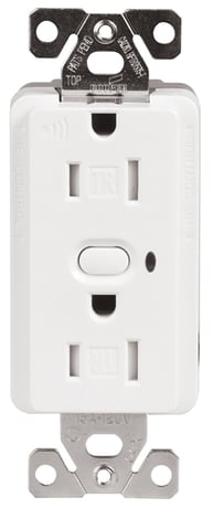
Product Picture


1 - Delayed OFF Time
Press and Hold sequence for Delayed OFF. Turns off the receptacle after a set time interval. The default is 10 seconds with available values from 0 to 127 secsSize: 1 byte
Default: 10
Minimum: 0
Maximum: 127
Possible values
| From | To | Desription |
|---|---|---|
| 0 | 127 | Delayed OFF Time |
2 - Panic ON Time
Time interval for receptacle to be ON when Panic Mode is enabledSize: 1 byte
Default: 1
Minimum: 0
Maximum: 127
Possible values
| From | To | Desription |
|---|---|---|
| 0 | 127 | Interval after which device will turn ON during panic mode |
3 - Panic OFF Time
Time interval for receptacle to be ON when Panic Mode is enabledSize: 1 byte
Default: 1
Minimum: 0
Maximum: 127
Possible values
| From | To | Desription |
|---|---|---|
| 0 | 127 | Interval after which device will turn OFF during panic mode |
5 - Power Up State
1 = OFF 2 = ON 3 = Last StateSize: 1 byte
Default: 1
Minimum: 1
Maximum: 3
Possible values
| From | To | Desription |
|---|---|---|
| 1 | 1 | Turn OFF when power is restored |
| 2 | 2 | Turn ON when power is restored |
| 3 | 3 | Return to last state when power is restored |
6 - Panic Mode Enabled
0=OFF 1=ONSize: 1 byte
Default: 0
Minimum: 0
Maximum: 1
Possible values
| From | To | Desription |
|---|---|---|
| 0 | 0 | Disable Panic Mode |
| 1 | 1 | Enable Panic Mode |
13 - BLUE LED Brightness level while the receptacle is ON
Light Intensity of Indicator LEDSize: 1 byte
Default: 3
Minimum: 0
Maximum: 4
Possible values
| From | To | Desription |
|---|---|---|
| 0 | 0 | Indicator light stays OFF |
| 1 | 4 | Increase the brightness of indicator light |
14 - BLUE LED Brightness level while the receptacle is OFF
Light Intensity of Indicator LEDSize: 1 byte
Default: 1
Minimum: 0
Maximum: 4
Possible values
| From | To | Desription |
|---|---|---|
| 0 | 0 | Indicator light stays OFF |
| 1 | 4 | Increase the brightness of indicator light |
1. To include this device in a Z-Wave network, select the command on your Z Wave controller for inclusion (Install, Add Device, Add Node, Include Device, etc.). Then press the device ON/OFF button one time to include it in the network. 2. Based on the controller, the controller may ask you to scan the QR code or manually enter 5 digit code under the QR code to install the device as a secured device. You may find this QR code on the device or included in device packaging. 3. After the Device is added to the network, the blue indicator LED will stop blinking. This indicates the device is installed in the Z-Wave network.
1. To exclude this device from a Z-Wave network, select the setting on your Z-Wave controller for exclusion (Uninstall, Remove Device, Remove Node, Exclude Device, etc.). 2. Once your controller is in exclusion mode, press the device ON/OFF button one time to exclude it from the network. The LED will start blinking.
Please use this procedure only when the network primary controller is missing or otherwise inoperable The device could be reset locally. This will cause the device to be excluded from its network and restore to factory default. Before leaving the network the switch will send a notification to the controller indicating its departure from the Z-Wave network. 1. Turn the device ON. 2. Press and hold ON/OFF button for 20 second till the LED flashes for the third time. 3. Release the ON/OFF button. 4. LED will start flashing rapidly. Once the LED starts blinking slowly, that indicates the device is not part of the network.
| Type | Value(s) |
|---|