Aeotec
Smart Boost Timer Switch
ZWA006-C
On/Off Power Switch
HW: 2 FW: 1.00:01.00
ZM5101
6.81.01
0x0371 (881)
0x0003 (3)
0x00B4 (180)
ZC10-18106255
2018-10-05 17:26:29.532475
N/A
Enhanced 232 Slave
Always On Slave
Yes
The Aeotec Smart Boost Timer Switch is a Z-Wave Plus enabled device and can be included/operated in any Z-Wave™ network with other Z-Wave™ certified devices from other manufacturers and/or other applications. All non-battery operated nodes within the network will act as repeaters regardless of vendor to increase reliability of the network.
The Aeotec Smart Boost Timer Switch is a Z-Wave Plus enabled device and can be included/operated in any Z-Wave™ network with other Z-Wave™ certified devices from other manufacturers and/or other applications. All non-battery operated nodes within the network will act as repeaters regardless of vendor to increase reliability of the network. The Aeotec Smart Boost Time Switch supports consumption meter function. When the device has been included in the network, it will report the consumption power periodically. It is also a high output countdown timer that can be used to control immersion heater elements or other electrical appliances rated up to 16A. On the product, four simple white LEDs are used to show the user how much time is left to run. Pressing the switch whilst the unit is operating allows the user to cancel the timing program,and the memory function of the timer will remember the last period selected.
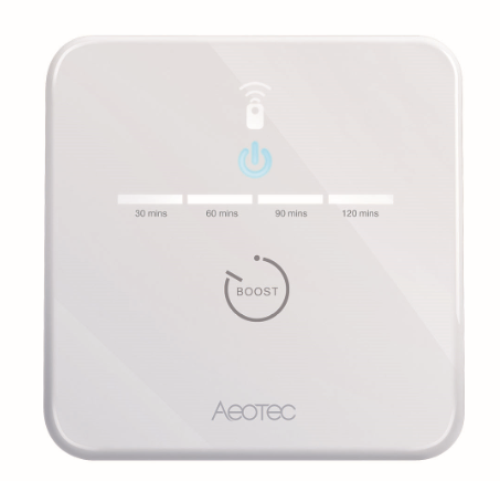
Product Picture


1 - Power out action
Action in case of power out. This parameter is used to configure the device state after power on.Size: 1 byte
Default: 3
Minimum: 0
Maximum: 0
Possible values
| From | To | Desription |
|---|---|---|
| 0 | 0 | keep the last state when re-power on |
| 1 | 1 | power on |
| 2 | 2 | power off |
| 3 | 3 | return to standard schedule (see schedule command class) so this would either be on or off depending on schedule and the time. |
2 - LED status
Configure LED (except boost) to be off irrespective of switch status.Size: 1 byte
Default: 1
Minimum: 0
Maximum: 0
Possible values
| From | To | Desription |
|---|---|---|
| 0 | 2 | 0 - disable all LED except for boost 1 - enable all LED indication 2 - Momentary mode (LED turns on for 5 seconds, then turn off LED) |
3 - Auto off timer
Timer acts as auto off after specified minutes, setting is set in seconds.Size: 4 bytes
Default: 0
Minimum: 0
Maximum: 0
Possible values
| From | To | Desription |
|---|---|---|
| 0 | 86400 | 0 - no auto off with timer 1 ~ 86400 auto off after this specified time, unit second. |
4 - Current overload protection
Current and overload protectionSize: 1 byte
Default: 1
Minimum: 0
Maximum: 0
Possible values
| From | To | Desription |
|---|---|---|
| 0 | 1 | 0 - disable current and overload protection 1 - enable current and overload protection |
5 - Boost time
Configure boost time interval, unit minute.Size: 2 bytes
Default: 30
Minimum: 0
Maximum: 0
Possible values
| From | To | Desription |
|---|---|---|
| 1 | 255 | When user press the boost button one time, the boost time will increase 30 (the value can be changed) minutes. |
7 - LED threshold setting
This parameter is used to configure the power led threshold, unit W. When the load <= 100W, the power led will indicate yellow. When the load > 100W, the power led will indicate orange. When no load, the power led will indicate white.Size: 2 bytes
Default: 100
Minimum: 0
Maximum: 0
Possible values
| From | To | Desription |
|---|---|---|
| 0 | 3000 | 0~3000 enabled threshold |
20 - kWh threshold setting
Threshold settings for energy kWh. When the energy above the threshold, it will send a meter report command to gateway.Size: 2 bytes
Default: 100
Minimum: 0
Maximum: 0
Possible values
| From | To | Desription |
|---|---|---|
| 0 | 10000 | 0 - disable report 1 ~ 10000 - enable report |
21 - Watt threshold setting
Threshold settings for Watt automatic report, unit W. When Watt above the threshold, it will send a meter report command to gateway.Size: 2 bytes
Default: 100
Minimum: 0
Maximum: 0
Possible values
| From | To | Desription |
|---|---|---|
| 0 | 2500 | 0 - disable 1 ~ 2500 - enable |
22 - Current threshold setting
Threshold settings for Current automatic report, unit 0.1A. When current above the threshold, it will send a meter report command to gateway.Size: 2 bytes
Default: 0
Minimum: 0
Maximum: 0
Possible values
| From | To | Desription |
|---|---|---|
| 0 | 130 | 0 - disable 1 ~ 130 - enable |
23 - Watt report interval
Watt automatic report interval, unit second.Size: 4 bytes
Default: 600
Minimum: 0
Maximum: 0
Possible values
| From | To | Desription |
|---|---|---|
| 0 | 0 | disable |
| 30 | 65535 | enable |
24 - kWh report interval
kWh automatic report interval, unit second.Size: 4 bytes
Default: 600
Minimum: 0
Maximum: 0
Possible values
| From | To | Desription |
|---|---|---|
| 0 | 0 | disable |
| 30 | 65535 | enable |
25 - Voltage report interval
Voltage automatic report interval, unit second.Size: 4 bytes
Default: 600
Minimum: 0
Maximum: 0
Possible values
| From | To | Desription |
|---|---|---|
| 0 | 0 | disable |
| 30 | 65535 | enable |
26 - Current report interval
Current automatic report interval, unit second.Size: 4 bytes
Default: 600
Minimum: 0
Maximum: 0
Possible values
| From | To | Desription |
|---|---|---|
| 0 | 0 | disable |
| 30 | 65535 | enable |
1. Power on the device, and the power led will blink blue slowly. 2. Put the Z-Wave Primary Controller into inclusion mode (If you don’t know how to do this, refer to its manual) 3. Press and hold the action button, and when the yellow LED is on, release the button. It indicates the device has enter learn mode. 4. If added successfully, the power LED will remain green for 2 seconds, then turn off.
1. Power on the device. 2. Put the Primary Controller into exclusion mode (If you don’t know how to do this refer to its manual) 3. Press and hold the action button, and when the purple LED turns on, release the button. This indicates that the device has entered learn mode. If removal is successful, the blue LED will blink slowly.
Please use this procedure only when the primary controller is missing or inoperable. 1. Make sure the device has been powered. 2. Press and hold the action button for 15 seconds. When the red LED turns on, release the button. Then, the device will enter factory reset mode. If the reset is successful, the LED will blink blue slowly.
Boost Mode 1. Power on the device. a) Press and hold the button about 1 second, when the power LED turns white, release the button. Then the 1st boost time LED will turn on. This indicates that the device entered boost mode. The switch will turn on immediately and will turn off after 30 minutes (This time can be changed through Configuration Parameter 5). b) Press and hold the button about 1 second after doing a), when the power LED turns white, release the button. The 1st and 2nd boost time LEDs will turn on, which means the switch will turn off after 60 minutes. c) Press and hold the button about 1 second after doing b), when the power LED turns white release the button. The 1st, 2nd and 3rd boost time LEDs will turn on, which means the switch will turn off after 90 minutes. d) Press and hold the button about 1 second after doing c), when the power LED turns white release the button. The 1st, 2nd, 3rd, and 4th boost time LEDs will turn on, which means the switch will turn off after 120 minutes. e) Press and hold the button about 1 second after doing d), when the power LED turn off release the button. Then all of the boost time leds will turn off, which indicates that boost mode has been exited. 2. Press and hold the button about 5 seconds. a) When the power LED turns green, release the button, and the device will enter an override schedule state. At this state, the schedule task doesn’t work. The switch can only be turned on or off from the gateway. b) When the power LED turns red, release the button, and the device will exit the override schedule state.
| Type | Value(s) |
|---|
| Sensor type |
|---|
| Power |
| Meter type |
|---|
| Electric Meter Consumption |