Nortek
GoControl Plug-In Switch Series 500
PD300EMZ5-1
Light Dimmer Switch
HW: 4 FW: 1.43
ZM5101
6.51.08
0x014F (335)
0x5044 (20548)
0x3533 (13619)
ZC10-18106267
2018-10-12 17:26:39.339166
N/A
Enhanced 232 Slave
Always On Slave
Plug in device for a dimmable light fixture for use in home automation systems. Includes a long-life LED nightlight, Energy Monitoring capability, inadvertent activation protection and Over The Air upgradable.
The PD300EMZ5-1 is a plug in the wall device designed to control dimmable lamps providing the ideal mood for every situation. Supporting Energy Monitoring the PD300EMZ5-1 will provide both a visual indication of the amount of energy the connected device is using, and also transmit this information to the Z-Wave hub for tracking purposes. Dual long life LEDs will also act as a night light when the load is off. The integrated button can be used to turn the connected device on / off, but it can also be temporarily disabled to eliminate the inadvertent operation of the device. With Over The Air upgrading supported, this device can be seamlessly updated to the most recent firmware and software features. Finally, as a Z-Wave plus product, it’s 30% longer range is ideal for easily creating a strong Z-Wave mesh network for an easier installation and more reliable operation.
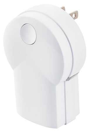
Product Picture


2 - LED Intnesity
Set the intensity of the LED.Size: 1 byte
Default: 100
Minimum: 0
Maximum: 0
Possible values
| From | To | Desription |
|---|---|---|
| 0 | 100 | 0 = OFF. 1 = Very Dim. 100 = Full Brightness. |
3 - Night Light
Configures the function of the integrated night lightSize: 1 byte
Default: 1
Minimum: 0
Maximum: 0
Possible values
| From | To | Desription |
|---|---|---|
| 0 | 3 | 0 - LED ON when the load is on and OFF when the load is off. 1 - LED OFF when the load is on, and ON when the load is off. 2 - LED is always on. 3 - LED is always off. |
7 - Remote Dim Step
Defines the number of steps the dimmer takes from full ON to OFF or OFF to ON for Remote devices.Size: 1 byte
Default: 3
Minimum: 0
Maximum: 0
Possible values
| From | To | Desription |
|---|---|---|
| 1 | 99 | # - Number of remote dimmer steps |
8 - Remote Dim Time
Defines the timing between the steps for remote dimmers.Size: 2 bytes
Default: 1
Minimum: 0
Maximum: 0
Possible values
| From | To | Desription |
|---|---|---|
| 1 | 255 | # - Remote Dim Time in mS |
9 - Local Dim Step
Defines the number of steps the dimmer takes from full ON to OFF or OFF to ON for attached devices.Size: 1 byte
Default: 3
Minimum: 0
Maximum: 0
Possible values
| From | To | Desription |
|---|---|---|
| 1 | 99 | # - Number of attached dimmer steps |
11 - Power Monitoring
Turns Power Monitoring ON or OFFSize: 1 byte
Default: 1
Minimum: 0
Maximum: 0
Possible values
| From | To | Desription |
|---|---|---|
| 0 | 1 | 0 - Power Monitoring OFF. 1 - Power Monitoring ON |
12 - Local Power Use Reporting
Sets the duration the LED will change color to indicate the amount of energy being used.Size: 2 bytes
Default: 60
Minimum: 0
Maximum: 0
Possible values
| From | To | Desription |
|---|---|---|
| 1 | 255 | 1 - 254 - Number of seconds LED displays power level usage. 255 - Power Level usage continuous ON. |
13 - Energy monitoring
Reports the total accumulated Kilowatt Hours (kWh) and the instantaneous Watts being consumed by the load.Size: 2 bytes
Default: 6
Minimum: 0
Maximum: 0
Possible values
| From | To | Desription |
|---|---|---|
| 0 | 255 | 0 - Automatic reporting OFF. 11-255 Number of minutes between automatic reporting (Default = 6) |
16 - Local Dim Time
Defines the timing between the steps for local attached dimmers.Size: 2 bytes
Default: 1
Minimum: 0
Maximum: 0
Possible values
| From | To | Desription |
|---|---|---|
| 1 | 255 | # - Local Dim Time in mS |
17 - All Switch Dim Step
Defines the number of steps switches takes from full ON to OFF or OFF to ON for all devices when an All Switch command is received.Size: 1 byte
Default: 3
Minimum: 0
Maximum: 0
Possible values
| From | To | Desription |
|---|---|---|
| 1 | 99 | # - Number of All switch steps |
18 - All Switch Dim Time
Defines the timing between the steps for all switches when an All Switch command is received.Size: 2 bytes
Default: 1
Minimum: 0
Maximum: 0
Possible values
| From | To | Desription |
|---|---|---|
| 1 | 255 | # - Local Dim Time in mS |
With your Controller in Discovery or Add Mode, tap the button on the face of the outlet. The LED will blink slowly when in ADD Mode. You should see an indication on your Controller that the “device was added” to the network and the LED will stop blinking. The device will appear in the list of Switches. It should display as a switch.
Set the Controller into Removal Mode and follow its instruction to delete the PD300EMZ5-1 from the Controller. Remove the switch by tapping the button on the face of the outlet 2 times. The LED will begin blinking slowly for 10 seconds indicating that it has been removed. You should see an indication on your Controller that the “device was removed” from the network.
In the event that your primary Controller is lost or otherwise inoperable, to reset the PD300EMZ5-1 and clear all network information, follow these steps: 1. Tap the button on the face of the outlet five (5) times. 2. Press and hold the button for 15 seconds. The LED will increasingly blink faster to indicate that a Reset is taking place.
| Type | Value(s) |
|---|
| Meter type |
|---|
| Electric Meter Consumption |