FIBARO
Wall Outlet
FGWOx-011
On/Off Power Switch
HW: 1 FW: 5.00:05.00
ZM5101
6.81.01
0x010F (271)
0x1F01 (7937)
0x1000 (4096)
ZC10-19026377
2019-02-01 17:38:31.377306
N/A
Enhanced 232 Slave
Always On Slave
FIBARO Walli Outlet is a smart electrical outlet designed to control electrical devices via Z-Wave network.
FIBARO Walli Outlet is a smart electrical outlet designed to control electrical devices via Z-Wave network. It measures active power and energy consumed by the controlled load. You can install it with provided cover plate or other compatible. Main features of FIBARO Walli Outlet: - Can turn ON/OFF plugged device remotely. - Available in two versions for plug types: o Type E, o Type F. - Can be used with provided cover plate or one of the following: o GIRA – System 55 (Standard 55, E2, Event, Event Clear), o Legrand – Céliane, o Schneider – Odace. - Active power and energy consumption metering. - Displays current load using multicolour LED frame (with FIBARO cover plate). - Supports Z-Wave network Security Modes: S0 with AES-128 encryption and S2 Authenticated with PRNG-based encryption. - Works as Z-Wave signal repeater (all non-battery operated devices within the network will act as repeaters to increase reliability of the network). - May be used with all devices certified with the Z-Wave Plus certificate and should be compatible with such devices produced by other manufacturers.
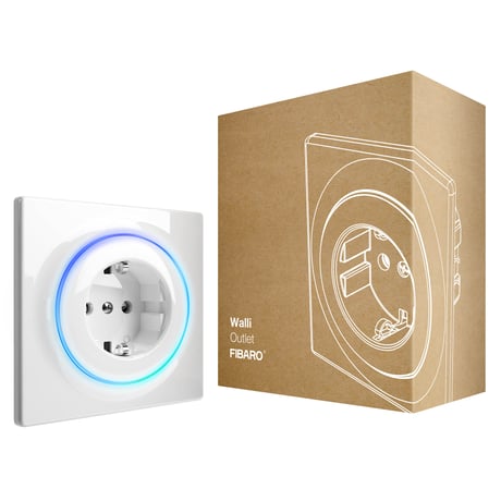
Product Picture


1 - Remember device state
This parameter determines how the device will react in the event of power supply failure (e.g. power outage).Size: 1 byte
Default: 1
Minimum: 0
Maximum: 0
Possible values
| From | To | Desription |
|---|---|---|
| 0 | 0 | remains switched off after restoring power |
| 1 | 1 | restores remembered state after restoring power |
2 - Overload safety switch
This function allows to turn off the controlled device in case o f exceeding the defined power. Controlled device can be turned back on via button or sending a control frame.Size: 4 bytes
Default: 0
Minimum: 0
Maximum: 0
Possible values
| From | To | Desription |
|---|---|---|
| 0 | 0 | function disabled |
| 10 | 36800 | (1.0-3680.0W, step 0.1W) – power threshold |
10 - LED frame – power limit
This parameter determines maximum active power. Exceeding it results in the LED frame flashing violet. Function is active only when parameter 11 is set to 8 or 9.Size: 4 bytes
Default: 36800
Minimum: 0
Maximum: 0
Possible values
| From | To | Desription |
|---|---|---|
| 500 | 36800 | (50.0-3680.0W, step 0.1W) – power threshold |
11 - LED frame – colour when ON
This parameter defines the LED colour when the device is ON. When set to 8 or 9, LED frame colour will change depending on he measured power and parameter 10. Other colours are set permanently and do not depend on power consumption.Size: 1 byte
Default: 8
Minimum: 0
Maximum: 0
Possible values
| From | To | Desription |
|---|---|---|
| 0 | 0 | LED disabled |
| 1 | 1 | White |
| 2 | 2 | Red |
| 3 | 3 | Green |
| 4 | 4 | Blue |
| 5 | 5 | Yellow |
| 6 | 6 | Cyan |
| 7 | 7 | Magenta |
| 8 | 8 | colour changes smoothly depending on measured power |
| 9 | 9 | colour changes in steps depending on measured power |
12 - LED frame – colour when OFF
This parameter defines the LED colour when the device is OFF.Size: 1 byte
Default: 0
Minimum: 0
Maximum: 0
Possible values
| From | To | Desription |
|---|---|---|
| 0 | 0 | LED disabled |
| 1 | 1 | White |
| 2 | 2 | Red |
| 3 | 3 | Green |
| 4 | 4 | Blue |
| 5 | 5 | Yellow |
| 6 | 6 | Cyan |
| 7 | 7 | Magenta |
13 - LED frame – brightness
This parameter allows to choose mode of 1st input (IN1). Change it depending on connected device.Size: 1 byte
Default: 100
Minimum: 0
Maximum: 0
Possible values
| From | To | Desription |
|---|---|---|
| 0 | 0 | LED disabled |
| 1 | 100 | (1-100% brightness) |
| 101 | 101 | brightness directly proportional to measured power |
| 102 | 102 | brightness inversely proportional to measured power |
30 - Alarm configuration - 1st slot
This parameter determines to which alarm frames and how the device should react. The parameters consist of 4 bytes, three most significant bytes are set according to the official Z-Wave protocol specification.Size: 4 bytes
Default: 0
Minimum: 0
Maximum: 0
Possible values
| From | To | Desription |
|---|---|---|
| 1 | 0 | [MSB] – Notification Type |
| 2 | 2 | Notification Value |
| 3 | 3 | Event/State Parameters |
| 4 | 4 | [LSB] – action |
31 - Alarm configuration - 2nd slot
This parameter determines to which alarm frames and how the device should react. The parameters consist of 4 bytes, three most significant bytes are set according to the official Z-Wave protocol specification.Size: 4 bytes
Default: 0
Minimum: 0
Maximum: 0
Possible values
| From | To | Desription |
|---|---|---|
| 1 | 1 | [MSB] – Notification Type |
| 2 | 2 | Notification Value |
| 3 | 3 | Event/State Parameters |
| 4 | 4 | [LSB] – action |
32 - Alarm configuration - 3rd slot
This parameter determines to which alarm frames and how the device should react. The parameters consist of 4 bytes, three most significant bytes are set according to the official Z-Wave protocol specification.Size: 4 bytes
Default: 0
Minimum: 0
Maximum: 0
Possible values
| From | To | Desription |
|---|---|---|
| 1 | 1 | [MSB] – Notification Type |
| 2 | 2 | Notification Value |
| 3 | 3 | Event/State Parameters |
| 4 | 4 | [LSB] – action |
33 - Alarm configuration - 4th slot
This parameter determines to which alarm frames and how the device should react. The parameters consist of 4 bytes, three most significant bytes are set according to the official Z-Wave protocol specification.Size: 4 bytes
Default: 0
Minimum: 0
Maximum: 0
Possible values
| From | To | Desription |
|---|---|---|
| 1 | 1 | [MSB] – Notification Type |
| 3 | 3 | Event/State Parameters |
| 4 | 4 | [LSB] – action |
| 0 | 0 | Notification Type |
| 2 | 2 | Notification Status |
34 - Alarm configuration - 5th slot
This parameter determines to which alarm frames and how the device should react. The parameters consist of 4 bytes, three most significant bytes are set according to the official Z-Wave protocol specification.Size: 4 bytes
Default: 0
Minimum: 0
Maximum: 0
Possible values
| From | To | Desription |
|---|---|---|
| 1 | 1 | [MSB] – Notification Type |
| 2 | 2 | Notification Value |
| 3 | 3 | Event/State Parameters |
| 4 | 4 | [LSB] – action |
35 - Alarm configuration – duration
This parameter defines duration of alarm sequence. When time set in this parameter elapses, alarm is cancelled, LED frame and relay restore normal operation, but do not recover state from before the alarm.Size: 2 bytes
Default: 600
Minimum: 0
Maximum: 0
Possible values
| From | To | Desription |
|---|---|---|
| 0 | 0 | infinite |
| 1 | 32400 | (1s-9h, 1s step) – duration |
45 - Associations – 2nd group
This parameter determines which actions will result in sending control frames to devices associated in 2nd group.Size: 1 byte
Default: 3
Minimum: 0
Maximum: 0
Possible values
| From | To | Desription |
|---|---|---|
| 1 | 1 | Power exceeds UP threshold |
| 2 | 2 | Power drops below DOWN threshold |
| 3 | 3 | Power exceeds UP threshold or drops below DOWN threshold |
46 - Associations – UP threshold
This parameter determines upper power threshold for 2nd association group (paramter 45). Exceeding it will result in sending value set in parameter 47. Cannot be lower than DOWN threshold (parameter 48).Size: 4 bytes
Default: 500
Minimum: 0
Maximum: 0
Possible values
| From | To | Desription |
|---|---|---|
| 100 | 36800 | (10-3680W, 0.1W step) – power threshold |
47 - Associations – UP threshold frame value
This parameter defines value sent to devices in 2nd association group when power exceeds UP threshold set in parameter 46 (using Basic Command Class).Size: 2 bytes
Default: 255
Minimum: 0
Maximum: 0
Possible values
| From | To | Desription |
|---|---|---|
| 0 | 0 | turn OFF |
| 1 | 99 | set level |
| 255 | 255 | turn ON |
48 - Associations – DOWN threshold
This parameter determines lower power threshold for 2nd association group (paramter 45). Exceeding it will result in sending value set in parameter 49.Size: 4 bytes
Default: 300
Minimum: 0
Maximum: 0
Possible values
| From | To | Desription |
|---|---|---|
| 0 | 36700 | (0-3670W, 0.1W step) – power threshold |
49 - Associations – DOWN threshold frame value
This parameter defines value sent to devices in 2nd association group when power drops below DOWN threshold set in parameter 48 (using Basic Command Class).Size: 2 bytes
Default: 0
Minimum: 0
Maximum: 0
Possible values
| From | To | Desription |
|---|---|---|
| 0 | 0 | turn OFF |
| 1 | 99 | set level |
| 255 | 255 | turn ON |
60 - Power reports – include self-consumption
This parameter determines whether the power measurements should include power consumed by the device itself.Size: 1 byte
Default: 0
Minimum: 0
Maximum: 0
Possible values
| From | To | Desription |
|---|---|---|
| 0 | 0 | Self-consumption not included |
| 1 | 1 | Self-consumption included |
61 - Power reports – on change
This parameter defines minimal change (from the last reported) in measured power that results in sending new report. For loads under 50W the parameter is irrelevant, report are sent every 5W change.Size: 2 bytes
Default: 15
Minimum: 0
Maximum: 0
Possible values
| From | To | Desription |
|---|---|---|
| 0 | 0 | reporting on change disabled |
| 1 | 500 | (1-500%, 1% step) – minimal change |
62 - Power reports – periodic
This parameter defines reporting interval for measured power. Periodic reports are independent from changes in value (parameter 61).Size: 2 bytes
Default: 3600
Minimum: 0
Maximum: 0
Possible values
| From | To | Desription |
|---|---|---|
| 0 | 0 | periodic reports disabled |
| 30 | 32400 | (30s-9h, 1s step) – time interval |
65 - Energy reports – on change
This parameter defines minimal change (from the last reported) in measured energy that results in sending new report.Size: 2 bytes
Default: 10
Minimum: 0
Maximum: 0
Possible values
| From | To | Desription |
|---|---|---|
| 1 | 500 | (0.01-5kWh, 0.01kWh step) – minimal change |
| 0 | 0 | reporting on change disabled |
66 - Energy reports – periodic
This parameter defines reporting interval for measured energy. Periodic reports are independent from changes in value (parameter 66).Size: 2 bytes
Default: 3600
Minimum: 0
Maximum: 0
Possible values
| From | To | Desription |
|---|---|---|
| 0 | 0 | periodic reports disabled |
| 30 | 32400 | (30s-9h, 1s step) – time interval |
To add the device to the Z-Wave network manually: 1. Power the device. 2. Set the main controller in (Security/non-Security Mode) add mode (see the controller’s manual). 3. Quickly, three times click one of the buttons. 4. If you are adding in Security S2 Authenticated, scan the DSK QR code or input the underlined part of the DSK (on the device label). 5. LED will start blinking yellow, wait for the adding process to end. 6. Adding result will be confirmed by the Z-Wave controller’s message and the LED frame: - Green - successful (non-secure, S0, S2 non-authenticated), - Magenta - successful (Security S2 Authenticated), - Red – not successful. To add the device to the Z-Wave network using SmartStart: 1. Set the main controller in Security S2 Authenticated add mode (see the controller’s manual). 2. Scan the DSK QR code or input the underlined part of the DSK (on the device label). 3. Power the device. 4. Wait for the adding process to start (up to few minutes), which is signaled with yellow LED blinking. 5. Adding result will be confirmed by the Z-Wave controller’s message and the LED frame: - Green - successful (non-secure, S0, S2 non-authenticated), - Magenta - successful (Security S2 Authenticated), - Red – not successful.
To remove the device from the Z-Wave network: 1. Power the device. 2. Set the main controller into remove mode (see the controller’s manual). 3. Quickly, three times click the button. 4. LED will start blinking yellow, wait for the removing process to end. 5. Successful removing will be confirmed by the Z-Wave controller’s message and red LED colour.
FIBARO Walli Outlet is powered using DC power supply unit so it is always awake.
Reset procedure allows to restore the device back to its factory settings, which means all information about the Z-Wave controller and user configuration will be deleted. Resetting to factory defaults does not reset energy consumption memory. 1. Press and hold the button to enter the menu. 2. Release the button when the device glows yellow. 3. Quickly click the button to confirm. 4. Device will blink yellow to confirm. 5. After a few seconds the device will be restarted, which is signalled with the red LED colour.
| Type | Value(s) |
|---|
| Group | Type |
|---|---|
| Power Management | (Refer to parameters): State idle |
| System | (Refer to parameters): State idle |
| Meter type |
|---|
| Electric Meter Consumption |