ABUS
Z-Wave Door Lock
HomeTec Pro CFA3010
Door Lock - Keypad
HW: 1 FW: 1.00
ZM5101
6.81.01
0x0409 (1033)
0x0005 (5)
0x0003 (3)
ZC10-19076649
2019-02-19 20:42:40.362841
N/A
Enhanced 232 Slave
Listening Sleeping Slave
Yes
The ABUS HomeTec Pro Z-Wave door drive is the ideal solution for comfortable access in house and apartment doors as well as office or service rooms.
The ABUS HomeTec Pro Z-Wave door lock drive is the ideal solution for comfortable access in house and apartment doors as well as office or service rooms. Once installed, these doors can then be conveniently and easily locked and unlocked via the app. The installation of the drive itself is also simple and easy. The maintenance-free and battery-operated drive can be installed safely with little effort and without cabling. The only prerequisite is a door cylinder with emergency function, which has on the inside of the door a projection of seven to 12 millimeters. The emergency function ensures that the door can continue to be opened and closed with the conventional key.
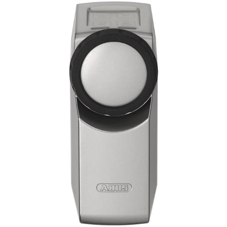
Product Picture


1 - Latch holding time
Current holding time of latch, settable to intervals of between 1 and 20 seconds.Size: 1 byte
Default: 3
Minimum: 0
Maximum: 0
Possible values
| From | To | Desription |
|---|---|---|
| 1 | 20 | Holding time of the latch settable from 1 to 20 seconds |
2 - Lact force
Setting of current torque during travel of latch - 1 high (max.) - 2 medium (standard) - 3 low (min.)Size: 1 byte
Default: 2
Minimum: 0
Maximum: 0
Possible values
| From | To | Desription |
|---|---|---|
| 1 | 3 | Seeting of current torque during travel of latch 1 is high, 2 medium and 3 low |
3 - Acoustic signal
Setting of acoustic signals to the following values: - 1 all signals inactive - 2 signal only at start of travel - 3 signal when latch position is reached - 4 signal when locked position is reached - 5 signal when end position is reached Button, lowbattery and error/alarm signals cannot be changed.Size: 1 byte
Default: 3
Minimum: 0
Maximum: 0
Possible values
| From | To | Desription |
|---|---|---|
| 1 | 5 | 1 all signals, 2 signal only, 3 signal when latch position is reached, 4 signal when locked position is reached, 5 end position |
4 - Travel path
Current setting of travel path at drive that is intended and/ or allowed to be travelled: - 1 Automatic / normal (travel according to teach-in run parameters) - 2 in case of multiple locking only one locking action - 3 motor travel from window tilt position is allowed (ABUS FCA3000)Size: 1 byte
Default: 1
Minimum: 0
Maximum: 0
Possible values
| From | To | Desription |
|---|---|---|
| 1 | 3 | 1 automatic, 2 in case of multiple locking only one locking action, 3 motor travel from window tilt position is allowed |
5 - Touch field
Current setting of touch field function: - 1 all active - 2 only operating buttons active - 3 all inactive - 4 only latch pull inactiveSize: 1 byte
Default: 1
Minimum: 0
Maximum: 0
Possible values
| From | To | Desription |
|---|---|---|
| 1 | 4 | 1 all active, 2 only operating buttons active, 3all inactive, only latch |
6 - Bolt force
Setting of current torque during travel of bolt: - 1 Automatic / normal (travel according to teach-in run parameters) - 2 maximumSize: 1 byte
Default: 1
Minimum: 0
Maximum: 0
Possible values
| From | To | Desription |
|---|---|---|
| 1 | 2 | 1 automatic(normal), 2 maximum |
250 - Lock status
Status of lock: - 0 unknown - 1 open - 2 unlocked - 3 1x locked - 4 2x locked - 5 locked (end stop) - 6 multiple lockingSize: 1 byte
Default: 0
Minimum: 0
Maximum: 0
Possible values
| From | To | Desription |
|---|---|---|
| 0 | 127 | 1 open, 2 inlocked, 3 locked 1x,4 is 2x locked, 5 locked, 6 multiple locking |
251 - Travel cycle latch
Counter, how often latch was actuatedSize: 1 byte
Default: 1
Minimum: 0
Maximum: 0
Possible values
| From | To | Desription |
|---|---|---|
| 0 | 127 | Counter how ofter latch was actuated |
252 - Travel cycles unlock
Counter, how often travel in „Unlocked“ directionSize: 1 byte
Default: 1
Minimum: 0
Maximum: 0
Possible values
| From | To | Desription |
|---|---|---|
| 0 | 127 | Counter how often travel in "unlocked" direction |
253 - Travel cycles locked
Counter, how often travel in „Locked“ directionSize: 1 byte
Default: 1
Minimum: 0
Maximum: 0
Possible values
| From | To | Desription |
|---|---|---|
| 0 | 127 | Counter how often travel in locked direction |
254 - ABUS Firmware version
Display ABUS firmware version, e.g. 1.05Size: 2 bytes
Default: 1
Minimum: 0
Maximum: 0
Possible values
| From | To | Desription |
|---|---|---|
| 0 | 127 | Displays the ABUS firmware version e.g. 1.05 |
Inclusion/Exclusion On factory default the device does not belong to any Z-Wave network. The device needs to be added to an existing wireless network to communicate with the devices of this network. This process is called Inclusion. Devices can also be removed from a network. This process is called Exclusion. Both processes are initiated by the primary controller of the Z-Wave network. This controller is turned into exclusion respective inclusion mode. Inclusion and Exclusion is then performed doing a special manual action right on the device. Process: 1. At first switch the primary Z-Wave controller to Inclusion or Exclusion mode 2. Now press the two arrow keys on the drive for 3 seconds until the left LED lights up green. This indicates the management mode. 3. Press the „lock“ button to start in- or exclusion, depending on what was previously set on the primary Z-Wave controller. 4. Both LEDs flash green to indicate that the unit is ready. 5. If the in- or exclusion is successful or if a timeout occurs, the green LED on the right goes out and the flashing ends. Please also note the transcription of the primary Z-Wave controller. 6. Pressing the „Unlock“ button will now also terminate the management mode.
Inclusion/Exclusion On factory default the device does not belong to any Z-Wave network. The device needs to be added to an existing wireless network to communicate with the devices of this network. This process is called Inclusion. Devices can also be removed from a network. This process is called Exclusion. Both processes are initiated by the primary controller of the Z-Wave network. This controller is turned into exclusion respective inclusion mode. Inclusion and Exclusion is then performed doing a special manual action right on the device. Process: 1. At first switch the primary Z-Wave controller to Inclusion or Exclusion mode 2. Now press the two arrow keys on the drive for 3 seconds until the left LED lights up green. This indicates the management mode. 3. Press the „lock“ button to start in- or exclusion, depending on what was previously set on the primary Z-Wave controller. 4. Both LEDs flash green to indicate that the unit is ready. 5. If the in- or exclusion is successful or if a timeout occurs, the green LED on the right goes out and the flashing ends. Please also note the transcription of the primary Z-Wave controller. 6. Pressing the „Unlock“ button will now also terminate the management mode.
Reset to factory default This device also allows to be reset without any involvement of a Z-Wave controller. Important note: this procedure should only be used when the primary controller is inoperable. Push the two arrow buttons for 3 seconds until the left LED lights up green. Then push the down arrow until the left LED lights up red. Press the „Close“ key to open the menu item. Now press „arrow down“ again until both LEDs on the drive light up red. Push the Enter-button for 3 seconds until both LEDs are flashing. Then push the Enter-button again for 3 seconds to confirm the reset to factory default. After that, all settings are deleted. After a factory reset, the drive (road and motor drive) must be taught-in again before the drive can be integrated into the Z-Wave system again. The device sends the following notifications to the central controller: • Manual Lock and Unlock operation (0x06 - 0x01/0x02) • RF Lock and Unlock Operation (0x06 - 0x03/0x03) • Lock Jammed (0x06 - 0x0B)
Enable Fallback to S0 Security If your Z-Wave Gateway/Controller does not support the S2 standard, inclusion is not possible immediately. To perform an inclusion, the S0 standard must be activated manually. (Since the Z-Wave S0 standard has a minimal security risk during teach-in, it is deactivated by default for the entry solution). Press the two arrow keys for 3 seconds until the left LED lights up green. This indicates the management mode. Press both arrow keys again for 3 seconds until the left LED flashes green. Now press the „up“ arrow key; the left LED flashes red. Confirm with the „Close“ key. The left LED flashes red, the right one lights up green = Standard S2. Press the down arrow key; the left LED flashes red and the right lights up red = S0 Security. Confirm the change from S2 to S0 by pressing the Close“ key.
| Type | Value(s) |
|---|
| Group | Type |
|---|---|
| Access Control | (Refer to parameters): State idle |
| Power Management | (Refer to parameters): State idle |
| System | (Refer to parameters): State idle |