CONFIO
4-Channel Power Strip
CT4R
Power Strip
HW: 1 FW: 1.01
ZM5101
6.81.03
0x0419 (1049)
0x4000 (16384)
0xC001 (49153)
ZC10-19066543
2019-05-31 18:07:09.222341
N/A
Enhanced 232 Slave
Always On Slave
Quad Switch CT4R is a miniature micromodule which can control Four Relay switches enable ON/OFF loads.
Quad.Switch CT4R is a miniature micromodule to operate in AC mains. On AC mains it operates with the common neutral load. It has the following features • Four Relay switches enable ON/OFF control of Regular loads. • Typical Regular relay loads (4R) are light sources (incandescent bulbs, CFL, LED lamps… etc), heaters, fans, air-conditioners, fridges, door openers, and other utility appliances. • The Quad switch CT4R also operates as a repeater within the Z-Wave network it is associated with.
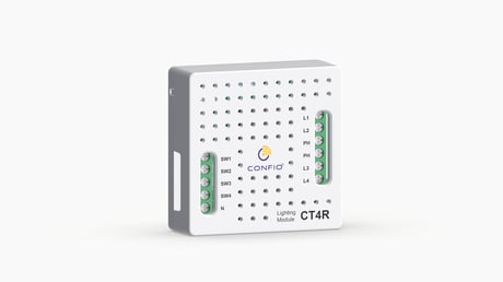
Product Picture


1 - Power ON state for Load1 (L1)
This parameter decides the power ON state (when the module is powered ON) of Load1 (L1). This parameter provides two options either power ON to memory (previous state as it was before power OFF) or present switch position.Size: 1 byte
Default: 0
Minimum: 0
Maximum: 0
Possible values
| From | To | Desription |
|---|---|---|
| 0 | 1 | 0: Memory, 1: Switch S1 |
2 - Power ON state for Load2 (L2)
This parameter decides the power ON state (when the module is powered ON) of Load2 (L2). This parameter provides two options either power ON to memory (previous state as it was before power OFF) or present switch position.Size: 1 byte
Default: 0
Minimum: 0
Maximum: 0
Possible values
| From | To | Desription |
|---|---|---|
| 0 | 1 | 0: Memory, 1: Switch S2 |
3 - Power ON state for Load3 (L3)
This parameter decides the power ON state (when the module is powered ON) of Load3 (L3). This parameter provides two options either power ON to memory (previous state as it was before power OFF) or present switch position.Size: 1 byte
Default: 0
Minimum: 0
Maximum: 0
Possible values
| From | To | Desription |
|---|---|---|
| 0 | 1 | 0: Memory, 1: Switch S3 |
4 - Power ON state for Load4 (L4)
This parameter decides the power ON state (when the module is powered ON) of Load4 (L4). This parameter provides two options either power ON to memory (previous state as it was before power OFF) or present switch position. Upcoming parameter 05, 06, 07, 08 comes in conflict with parameter 09 when set to value 02, 03, 04. Parameter 09 designed to combine multiple relays to handle a higher wattage load. The user must set this parameter to 0, before enabling relay combination via parameter 09 to avoid a hazardous situation.Size: 1 byte
Default: 0
Minimum: 0
Maximum: 0
Possible values
| From | To | Desription |
|---|---|---|
| 0 | 1 | 0: Memory, 1: Switch S4 |
5 - Auto OFF for Load L1
This parameter decides the ON time duration for Load1 (L1). It ranges from 1 minute to 240 minutes i.e. 4 hours. Auto OFF counting starts as soon as L1 is turned ON either via S1 or GUI. Once duration expires the L1 turned off automatically. Setting this value to 0 (Zero) will disable auto OFF functionality.Size: 1 byte
Default: 0
Minimum: 0
Maximum: 0
Possible values
| From | To | Desription |
|---|---|---|
| 1 | 240 | 1 minute to 240 minutes (4 hours) |
6 - Auto OFF for Load L2
This parameter decides the ON time duration for Load2 (L2). It ranges from 1 minute to 240 minutes i.e. 4 hours. Auto OFF counting starts as soon as L2 is turned ON either via S2 or GUI. Once duration expires the L2 turned off automatically. Setting this value to 0 (Zero) will disable auto OFF functionality.Size: 1 byte
Default: 0
Minimum: 0
Maximum: 0
Possible values
| From | To | Desription |
|---|---|---|
| 1 | 240 | 1 minute to 240 minutes (4 hours) |
7 - Auto OFF for Load L3
This parameter decides the ON time duration for Load3 (L3). It ranges from 1 minute to 240 minutes i.e. 4 hours. Auto OFF counting starts as soon as L3 is turned ON either via S3 or GUI. Once duration expires the L3 turned off automatically. Setting this value to 0 (Zero) will disable auto OFF functionality.Size: 1 byte
Default: 0
Minimum: 0
Maximum: 0
Possible values
| From | To | Desription |
|---|---|---|
| 0 | 1 | 0: Memory, 1: Switch S2 |
| 1 | 240 | 1 minute to 240 minutes (4 hours) |
8 - Auto OFF for Load L4
This parameter decides the ON time duration for Load4 (L4). It ranges from 1 minute to 240 minutes i.e. 4 hours. Auto OFF counting starts as soon as L4 is turned ON either via S4 or GUI. Once duration expires the L4 turned off automatically. Setting this value to 0 (Zero) will disable auto OFF functionality.Size: 1 byte
Default: 0
Minimum: 0
Maximum: 0
Possible values
| From | To | Desription |
|---|---|---|
| 1 | 240 | 1 minute to 240 minutes (4 hours) |
9 - Combine Relays/endpoints
This parameter is designed to combine two or more relays to handle higher wattage load current. 1: L1 only operates with S1 and GUI master. 2: L1 & L2 only operates with S1 and GUI master. 3: L1, L2, & L3 only operates with S1 and GUI master. 4: L1, L2, L3, & L4 only operates with S1 and GUI master. Default: 1 L1 only operates with S1 and GUI masterSize: 1 byte
Default: 1
Minimum: 0
Maximum: 0
Possible values
| From | To | Desription |
|---|---|---|
| 1 | 4 | 1,2,3,4 |
10 - Switch S1 behavior
This parameter defines the behaviour of switch S1. If set to 0, it behaves like a regular switch (i.e. putting a switch to ON position will turn ON L1 and putting to OFF position will turn OFF L1) and if set to 1, it behaves like a toggle switch (i.e. putting the switch to either ON or OFF position makes L1 toggle). Default: 0 regular switches (i.e. ON-to-ON and OFF-to-OFF)Size: 1 byte
Default: 0
Minimum: 0
Maximum: 0
Possible values
| From | To | Desription |
|---|---|---|
| 0 | 1 | 0: regular switch (i.e. ON-to-ON and OFF-to-OFF), 1: toggle switch (ON-to-Toggle and OFF-to-Toggle) |
11 - Switch S2 behaviour
This parameter defines the behaviour of switch S2. If set to 0, it behaves like the regular switch (i.e. putting the switch to ON position will turn ON L2 and putting to OFF position will turn OFF L2) and if set to 1, it behaves like a toggle switch (i.e. putting the switch to either ON or OFF position makes L2 toggle). Default: 0 regular switches (i.e. ON-to-ON and OFF-to-OFF)Size: 1 byte
Default: 0
Minimum: 0
Maximum: 0
Possible values
| From | To | Desription |
|---|---|---|
| 0 | 1 | 0: regular switch (i.e. ON-to-ON and OFF-to-OFF), 1: toggle switch (ON-to-Toggle and OFF-to-Toggle) |
12 - Switch S3 behaviour
This parameter defines the behaviour of switch S3. If set to 0, it behaves like the regular switch (i.e. putting a switch to ON position will turn ON L3 and putting to OFF position will turn OFF L3) and if set to 1, it behaves like a toggle switch (i.e. putting the switch to either ON or OFF position makes L3 toggle). Default: 0 regular switches (i.e. ON-to-ON and OFF-to-OFF)Size: 1 byte
Default: 0
Minimum: 0
Maximum: 0
Possible values
| From | To | Desription |
|---|---|---|
| 0 | 1 | 0: regular switch (i.e. ON-to-ON and OFF-to-OFF), 1: toggle switch (ON-to-Toggle and OFF-to-Toggle) |
13 - Switch S4 behaviour
This parameter defines the behaviour of switch S4. If set to 0, it behaves like the regular switch (i.e. putting the switch to ON position will turn ON L4 and putting to OFF position will turn OFF L4) and if set to 1, it behaves like a toggle switch (i.e. putting the switch to either ON or OFF position makes L4 toggle). Default: 0 regular switches (i.e. ON-to-ON and OFF-to-OFF)Size: 1 byte
Default: 0
Minimum: 0
Maximum: 0
Possible values
| From | To | Desription |
|---|---|---|
| 0 | 1 | 0: regular switch (i.e. ON-to-ON and OFF-to-OFF), 1: toggle switch (ON-to-Toggle and OFF-to-Toggle) |
14 - On board LED indications enable/disable
This parameter makes onboard LED indication to enable/disable. By default, this parameter is set to 1 (enable LED indications).Size: 1 byte
Default: 1
Minimum: 0
Maximum: 0
Possible values
| From | To | Desription |
|---|---|---|
| 0 | 1 | 0: disable, 1: enable |
15 - Local switch S1 enable/disable
This parameter makes local switch S1 either enable or disable. By default, this is set to 1 (enable S1).Size: 1 byte
Default: 1
Minimum: 0
Maximum: 0
Possible values
| From | To | Desription |
|---|---|---|
| 0 | 1 | 0: disable, 1: enable |
16 - Local switch S2 enable/disable
This parameter makes local switch S2 either enable or disable. By default, this is set to 1 (enable S2).Size: 1 byte
Default: 1
Minimum: 0
Maximum: 0
Possible values
| From | To | Desription |
|---|---|---|
| 0 | 1 | 0: disable, 1: enable |
17 - Local switch S3 enable/disable
This parameter makes local switch S3 either enable or disable. By default, this is set to 1 (enable S3).Size: 1 byte
Default: 1
Minimum: 0
Maximum: 0
Possible values
| From | To | Desription |
|---|---|---|
| 0 | 1 | 0: disable, 1: enable |
18 - Local switch S4 enable/disable
This parameter makes local switch S4 either enable or disable. By default, this is set to 1 (enable S4).Size: 1 byte
Default: 1
Minimum: 0
Maximum: 0
Possible values
| From | To | Desription |
|---|---|---|
| 0 | 1 | 0: disable, 1: enable |
The term “INCLUSION”, “ADDING”, “PARING” implies the same meaning. Inclusion is a process by which a new device (or a device which previously got out of Z-Wave network by force reset or exclusion process) can join a new or existing Z-Wave network. Basically, two steps are involved in the inclusion process, 1) Set Gateway/Controller into the inclusion mode (See gateway user manual) 2) Set device into the learn mode Learn mode can be invoked by a one-time short press of NODE_INFO key or three times ON press (within 5 seconds) of S1 key. User indication: Blinking of green LED shows successful inclusion.
The term “EXCLUSION”, “REMOVING”, “UNPAIRING” implies the same meaning. Exclusion is a process by which an already included device can be made to leave its existing Z-Wave network. Upon exclusion, all user configuration parameters are set to their default values. Exclusion of the device can be done in two steps, 1) Set Gateway/Controller into the exclusion mode (See gateway user manual) 2) Set device into the learn mode Learn mode can be invoked by a one-time press of NODE_INFO key or three times ON press (within 5 seconds) of S1 key. User indication: Blinking of red LED shows successful exclusion.
Device Reset can be invoked by press & hold NODE_INFO key for more than 10 seconds. User indication: Blinking of red LED shows a successful reset. The controller will be informed about this event via COMMAND_CLASS_DEVICE_RESET_LOCALLY command. Once the device resets, it will no longer be a part of the Z-Wave network and all the user configuration parameters are set to their default values. Note: Please use this procedure only when the network primary controller is missing or otherwise inoperable.
Support ""Over the Air Firmware Updating"" and “Z-Wave Security”.
| Type | Value(s) |
|---|