Widom
WiDom Smart Plug
WSP
On/Off Power Switch
HW: 255 FW: 0.02
ZM5101
6.81.04
0x0149 (329)
0x1214 (4628)
0x0700 (1792)
ZC10-19046462
2019-03-06 07:35:31.30902
N/A
Enhanced 232 Slave
Always On Slave
Smart Plug is able to detect overvoltage and/or overcurrent cases and through a multicolor LED can send alerts. Furthermore, it protects appliances from eventual overload. A very innovative design, which integrates a complex system that allows a precise energy consumption monitoring.
Smart Plug is able to detect overvoltage and/or overcurrent cases and through a multicolor LED can send alerts. Furthermore, it protects appliances from eventual overload. A very innovative design, which integrates a complex system that allows a precise energy consumption monitoring. The integration of these features in its very small size product, make it unique on the market. Alerts and visual feedback with RGB LED An RGB LED on the device provides visual feedback for overvoltage and / or overcurrent and overpower detection. Small size and innovative design The WiDom Smart Plug has an elegant design and small size that allows a perfect integration in any home environment. Monitoring of energy consumption Within the WiDom Smart Plug is integrated a very precise energy consumption meter that allows you to monitor the consumption of the connected equipment. Simplified device inclusion and exclusion WiDom Smart Plug can be included in any Z-Wave network and work with Z-Wave devices from any other company. WiDom Smart Plug, used as a constantly powered node, will act as a signal repeater to increase network reliability. WiDom Smart Plug is compatible with all Z-Wave certified controllers. Associations and Multiclick WiDom Smart Plug can control, through association, other devices of the Z-Wave network in which is included, when an event of overcurrent, overvoltage or events on the Push Button occur. It is possible to activate a multiclick recognition, for example, you can check with a single click the load connected to the Smart Plug and double-click the associated devices. Zero crossing - Contact protection technology To reduce the electrical stress on the relay contacts and ensure a longer life, the open / closed switching of the device always occur when the instantaneous value of voltage is 0. S2 Security The Smart Roller Shutter uses a strong and secure S2 protection system, which provides advanced security features and eliminates the risk of hacking of devices.
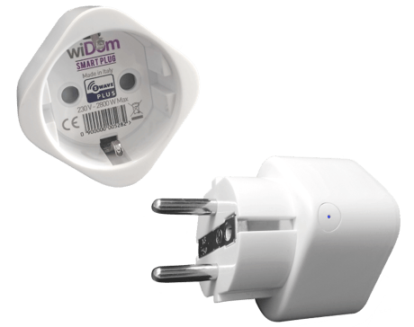
Product Picture


1 - Local load control
Defines which sequences of click control the local load.Size: 1 byte
Default: 3
Minimum: 0
Maximum: 0
Possible values
| From | To | Desription |
|---|---|---|
| 1 | 1 | 1 click turn ON/OFF the local load |
| 2 | 2 | 2 clicks turn ON/OFF the local load |
| 3 | 3 | 1 click or 2 clicks turn ON/OFF the local load |
2 - Level used to control the devices associated to group 4 (
Defines how to control the devices associated to 1 click event.Size: 1 byte
Default: 100
Minimum: 0
Maximum: 0
Possible values
| From | To | Desription |
|---|---|---|
| 0 | 0 | The associated devices are switched OFF |
| -1 | -1 | The associated devices are switched ON |
| 1 | 99 | The associated devices (dimmer, roller shutters) are set to the indicated level |
| 100 | 100 | If the relay is ON/OFF, the associated devices are ON/OFF |
3 - Level used to control the devices associated to group 5
Defines how to control the devices associated to 2 clicks event.Size: 1 byte
Default: 100
Minimum: 0
Maximum: 0
Possible values
| From | To | Desription |
|---|---|---|
| 0 | 0 | The associated devices are switched OFF |
| -1 | -1 | The associated devices are switched ON |
| 1 | 99 | The associated devices (dimmer, roller shutters) are set to the indicated level |
| 100 | 100 | If the relay is ON/OFF, the associated devices are ON/OFF |
4 - Overvoltage level
Defines the voltage level (in Volts) beyond which an overvoltage event is identified and the overvoltage timer is activated. The timer is reset when the event ceases, i.e. when the voltage returns below the overvoltage level. As soon as an overvoltage event occurs, the LED starts a BLUE blinking. If the overvoltage event ceases before the overvoltage timer expires, the blue blinking is stopped, otherwise the alarm is generated and the blinking reset is established by parameter 6.Size: 2 bytes
Default: 253
Minimum: 0
Maximum: 0
Possible values
| From | To | Desription |
|---|---|---|
| 110 | 260 | Defines the overvoltage level (in Volts) |
5 - Overvoltage Timer
Define the time (seconds) in which the voltage must persist above the overvoltage level so that an alarm is generated.Size: 2 bytes
Default: 5
Minimum: 0
Maximum: 0
Possible values
| From | To | Desription |
|---|---|---|
| 1 | 3600 | Overvoltage time interval (in seconds) after witch an alarm is generated |
6 - Define how to reset the overvoltage alarm and breaks off the blue blinking.
Size: 1 byte
Default: 0
Minimum: 0
Maximum: 0
Possible values
| From | To | Desription |
|---|---|---|
| 0 | 0 | Manual when the relay change its state through the Push Button |
| 1 | 1 | When the overvoltage event is terminated |
7 - Level used to control the devices associated to group 3
Define how to control the devices associated to the overvoltage alarmSize: 1 byte
Default: 0
Minimum: 0
Maximum: 0
Possible values
| From | To | Desription |
|---|---|---|
| 0 | 0 | The associated devices are switched OFF |
| -1 | -1 | The associated devices are switched ON |
| 1 | 99 | The associated devices (dimmer, roller shutters) are set to the indicated level |
8 - Overcurrent level
Defines the current level (in Amps) beyond which an overcurrent event is identified and the overcurrent timer is activated. The timer is reset when the event ceases, i.e. when the current returns below the overcurrent level. As soon as an overcurrent event occurs, the led starts a red blinking. If the overcurrent event ceases before the overcurrent timer expires, the red blinking is stopped, otherwise the alarm is generated and the blinking reset is established by parameter 10.Size: 1 byte
Default: 12
Minimum: 0
Maximum: 0
Possible values
| From | To | Desription |
|---|---|---|
| 1 | 12 | Defines the overcurrent level (in Amps) |
9 - Overcurrent Timer
Define the time (seconds) in which the current must persist above the overcurrent level so that an alarm is generated and the relay is opened.Size: 2 bytes
Default: 10
Minimum: 0
Maximum: 0
Possible values
| From | To | Desription |
|---|---|---|
| 1 | 3600 | Overcurrent time interval (in seconds) after witch an alarm is generated |
10 - Overcurrent Alarm Reset
Define how to reset the over-current alarm and breaks off the red blinking.Size: 1 byte
Default: 1
Minimum: 0
Maximum: 0
Possible values
| From | To | Desription |
|---|---|---|
| 0 | 0 | Manual when the relay change its state through the Push Button |
| 1 | 1 | When the over-voltage event is terminated |
11 - Level used to control the devices associated to group 2
Define how to control the devices associated to the overcurrent alarm.Size: 1 byte
Default: 0
Minimum: 0
Maximum: 0
Possible values
| From | To | Desription |
|---|---|---|
| 0 | 0 | The associated devices are switched OFF |
| -1 | -1 | The associated devices are switched ON |
| 1 | 99 | The associated devices (dimmer, roller shutters) are set to the indicated level |
Triple clicks on the integrated button
Triple clicks on the integrated button. As soon as the device has been removed form the network it will be reset to the factory setting.
| Type | Value(s) |
|---|
| Meter type |
|---|
| Electric Meter Consumption |