Vitrum
Vitrum VI EU on-off 6 triac 868.4MHz
01E06S263
On/Off Power Switch
HW: 1 FW: 5.50:01.01
ZM5202
6.71.03
0x010A (266)
0x8161 (33121)
0x2062 (8290)
ZC10-19106768
2019-10-03 18:20:40.541146
N/A
Enhanced 232 Slave
Always On Slave
The Vitrum switches are made with innovative techniques and materials: smooth surfaces and elegant lines, a hollowed glass that offers a stimulating tactile perception for a high-profile sensory impact, and a unique user experience.
Vitrum can easily be installed in common flush-mounting boxes, and does not require buses, control units or additional wiring. It uses the most widespread technologies in the world, and offers an advanced and intuitive user experience and is offered in different collections to choose the style that best suits your needs. The great versatility of Vitrum simplifies home automation and makes it available to everyone.
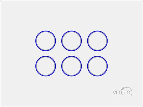
Product Image
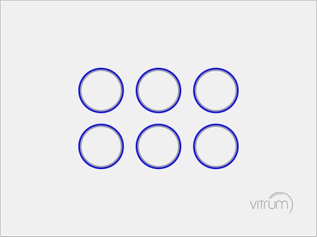


7 - Button N.1 Off status LED
Color of LED associated to push-button N.1 reporting an off state.Size: 1 byte
Default: 3
Minimum: 0
Maximum: 7
Possible values
| From | To | Desription |
|---|---|---|
| 0 | 7 | LED is off: 0: LED is off; 1: Red; 2: Green; 3: Blue; 4: Yellow; 5: Magenta; 6: Cyan; 7; White. |
8 - Button N.2 Off status LED
Color of LED associated to push-button N.2 reporting an off state.Size: 1 byte
Default: 3
Minimum: 0
Maximum: 7
Possible values
| From | To | Desription |
|---|---|---|
| 0 | 7 | 0: LED is off; 1: Red; 2: Green; 3: Blue; 4: Yellow; 5: Magenta; 6: Cyan; 7; White. |
9 - Button N.3 Off status LED
Color of LED associated to push-button N.3 reporting an off state.Size: 1 byte
Default: 3
Minimum: 0
Maximum: 7
Possible values
| From | To | Desription |
|---|---|---|
| 0 | 7 | 0: LED is off; 1: Red; 2: Green; 3: Blue; 4: Yellow; 5: Magenta; 6: Cyan; 7; White. |
10 - Button N.4 Off status LED
Color of LED associated to push-button N.4 reporting an off state.Size: 1 byte
Default: 3
Minimum: 0
Maximum: 7
Possible values
| From | To | Desription |
|---|---|---|
| 0 | 7 | 0: LED is off; 1: Red; 2: Green; 3: Blue; 4: Yellow; 5: Magenta; 6: Cyan; 7; White. |
11 - Button N.5 Off status LED
Color of LED associated to push-button N.5 reporting an off state.Size: 1 byte
Default: 3
Minimum: 0
Maximum: 7
Possible values
| From | To | Desription |
|---|---|---|
| 0 | 7 | 0: LED is off; 1: Red; 2: Green; 3: Blue; 4: Yellow; 5: Magenta; 6: Cyan; 7; White. |
12 - Button N.6 Off status LED
Color of LED associated to push-button N.6 reporting an off state.Size: 1 byte
Default: 3
Minimum: 0
Maximum: 7
Possible values
| From | To | Desription |
|---|---|---|
| 0 | 7 | 0: LED is off; 1: Red; 2: Green; 3: Blue; 4: Yellow; 5: Magenta; 6: Cyan; 7; White. |
13 - Button N.1 On status LED
Color of LED associated to push-button N.1 reporting an on state.Size: 1 byte
Default: 4
Minimum: 0
Maximum: 7
Possible values
| From | To | Desription |
|---|---|---|
| 0 | 7 | 0: LED is off; 1: Red; 2: Green; 3: Blue; 4: Yellow; 5: Magenta; 6: Cyan; 7; White. |
14 - Button N.2 On status LED
Color of LED associated to push-button N.2 reporting an on state.Size: 1 byte
Default: 4
Minimum: 0
Maximum: 7
Possible values
| From | To | Desription |
|---|---|---|
| 0 | 7 | 0: LED is off; 1: Red; 2: Green; 3: Blue; 4: Yellow; 5: Magenta; 6: Cyan; 7; White. |
15 - Button N.3 On status LED
Color of LED associated to push-button N.3 reporting an on state.Size: 1 byte
Default: 4
Minimum: 0
Maximum: 7
Possible values
| From | To | Desription |
|---|---|---|
| 0 | 7 | 0: LED is off; 1: Red; 2: Green; 3: Blue; 4: Yellow; 5: Magenta; 6: Cyan; 7; White. |
16 - Button N.4 On status LED
Color of LED associated to push-button N.4 reporting an on state.Size: 1 byte
Default: 4
Minimum: 0
Maximum: 7
Possible values
| From | To | Desription |
|---|---|---|
| 0 | 7 | 0: LED is off; 1: Red; 2: Green; 3: Blue; 4: Yellow; 5: Magenta; 6: Cyan; 7; White. |
17 - Button N.5 On status LED
Color of LED associated to push-button N.5 reporting an on state.Size: 1 byte
Default: 4
Minimum: 0
Maximum: 7
Possible values
| From | To | Desription |
|---|---|---|
| 0 | 7 | 0: LED is off; 1: Red; 2: Green; 3: Blue; 4: Yellow; 5: Magenta; 6: Cyan; 7; White. |
18 - Button N.6 On status LED
Color of LED associated to push-button N.6 reporting an on state.Size: 1 byte
Default: 4
Minimum: 0
Maximum: 7
Possible values
| From | To | Desription |
|---|---|---|
| 0 | 7 | 0: LED is off; 1: Red; 2: Green; 3: Blue; 4: Yellow; 5: Magenta; 6: Cyan; 7; White. |
25 - Output port connected to Button N.1
Output port connected to Button N.1. Remark: connecting a button to an output port already connected to another different button, will force the previously connected button to be automatically disconnectedSize: 1 byte
Default: 1
Minimum: 0
Maximum: 6
Possible values
| From | To | Desription |
|---|---|---|
| 0 | 6 | 0: Disconnected; 1: Button connected to Output Port 1; 2: Button connected to Output Port 2; 3: Button connected to Output Port 3; 4: Button connected to Output Port 4; 5: Button connected to Output Port 5; 6: Button connected to Output Port 6. |
26 - Output port connected to Button N.2
Output port connected to Button N.2. Remark: connecting a button to an output port already connected to another different button, will force the previously connected button to be automatically disconnectedSize: 1 byte
Default: 2
Minimum: 0
Maximum: 6
Possible values
| From | To | Desription |
|---|---|---|
| 0 | 6 | 0: Disconnected; 1: Button connected to Output Port 1; 2: Button connected to Output Port 2; 3: Button connected to Output Port 3; 4: Button connected to Output Port 4; 5: Button connected to Output Port 5; 6: Button connected to Output Port 6. |
27 - Output port connected to Button N.3
Output port connected to Button N.3. Remark: connecting a button to an output port already connected to another different button, will force the previously connected button to be automatically disconnectedSize: 1 byte
Default: 3
Minimum: 0
Maximum: 0
Possible values
| From | To | Desription |
|---|---|---|
| 0 | 6 | 0: Disconnected; 1: Button connected to Output Port 1; 2: Button connected to Output Port 2; 3: Button connected to Output Port 3; 4: Button connected to Output Port 4; 5: Button connected to Output Port 5; 6: Button connected to Output Port 6. |
28 - Output port connected to Button N.4
Output port connected to Button N.4. Remark: connecting a button to an output port already connected to another different button, will force the previously connected button to be automatically disconnectedSize: 1 byte
Default: 4
Minimum: 0
Maximum: 6
Possible values
| From | To | Desription |
|---|---|---|
| 0 | 6 | 0: Disconnected; 1: Button connected to Output Port 1; 2: Button connected to Output Port 2; 3: Button connected to Output Port 3; 4: Button connected to Output Port 4; 5: Button connected to Output Port 5; 6: Button connected to Output Port 6. |
29 - Output port connected to Button N.5
Output port connected to Button N.5. Remark: connecting a button to an output port already connected to another different button, will force the previously connected button to be automatically disconnectedSize: 1 byte
Default: 5
Minimum: 0
Maximum: 6
Possible values
| From | To | Desription |
|---|---|---|
| 0 | 6 | 0: Disconnected; 1: Button connected to Output Port 1; 2: Button connected to Output Port 2; 3: Button connected to Output Port 3; 4: Button connected to Output Port 4; 5: Button connected to Output Port 5; 6: Button connected to Output Port 6. |
30 - Output port connected to Button N.6
Output port connected to Button N.6. Remark: connecting a button to an output port already connected to another different button, will force the previously connected button to be automatically disconnectedSize: 1 byte
Default: 6
Minimum: 0
Maximum: 6
Possible values
| From | To | Desription |
|---|---|---|
| 0 | 6 | 0: Disconnected; 1: Button connected to Output Port 1; 2: Button connected to Output Port 2; 3: Button connected to Output Port 3; 4: Button connected to Output Port 4; 5: Button connected to Output Port 5; 6: Button connected to Output Port 6. |
31 - Basic Set On from Group 2
Value of the Basic Set command sent: 0: 99 (0x63) 1: 255 (0xFF)Size: 1 byte
Default: 1
Minimum: 0
Maximum: 1
Possible values
| From | To | Desription |
|---|---|---|
| 0 | 1 | 0: 99 (0x63) 1: 255 (0xFF) |
32 - Basic Set On from Group 3
Value of the Basic Set command sent: 0: 99 (0x63) 1: 255 (0xFF)Size: 1 byte
Default: 1
Minimum: 0
Maximum: 1
Possible values
| From | To | Desription |
|---|---|---|
| 0 | 1 | 0: 99 (0x63) 1: 255 (0xFF) |
33 - Basic Set On from Group 4
Value of the Basic Set command sent: 0: 99 (0x63) 1: 255 (0xFF)Size: 1 byte
Default: 1
Minimum: 0
Maximum: 1
Possible values
| From | To | Desription |
|---|---|---|
| 0 | 1 | 0: 99 (0x63) 1: 255 (0xFF) |
34 - Basic Set On from Group 5
Value of the Basic Set command sent: 0: 99 (0x63) 1: 255 (0xFF)Size: 1 byte
Default: 1
Minimum: 0
Maximum: 1
Possible values
| From | To | Desription |
|---|---|---|
| 0 | 1 | 0: 99 (0x63) 1: 255 (0xFF) |
35 - Basic Set On from Group 6
Value of the Basic Set command sent: 0: 99 (0x63) 1: 255 (0xFF)Size: 1 byte
Default: 1
Minimum: 0
Maximum: 1
Possible values
| From | To | Desription |
|---|---|---|
| 0 | 1 | 0: 99 (0x63) 1: 255 (0xFF) |
36 - Basic Set On from Group 7
Value of the Basic Set command sent: 0: 99 (0x63) 1: 255 (0xFF)Size: 1 byte
Default: 1
Minimum: 0
Maximum: 1
Possible values
| From | To | Desription |
|---|---|---|
| 0 | 1 | 0: 99 (0x63) 1: 255 (0xFF) |
206 - Buttons Max. Brightness
Maximum brightness of LEDs associated to push-buttons. Remark: value must be grater or equal than Parameter N.207.Size: 1 byte
Default: 100
Minimum: 5
Maximum: 100
Possible values
| From | To | Desription |
|---|---|---|
| 5 | 100 | LEDs maximum brightness |
207 - Buttons Min. Brightness
Maximum brightness of LEDs associated to push-buttons. Remark: value must be less or equal than Parameter N.206.Size: 1 byte
Default: 5
Minimum: 0
Maximum: 100
Possible values
| From | To | Desription |
|---|---|---|
| 0 | 100 | LED minum brightness. |
209 - Buzzer
Buzzer operating status.Size: 1 byte
Default: 1
Minimum: 0
Maximum: 1
Possible values
| From | To | Desription |
|---|---|---|
| 0 | 1 | 0: disabled 1: enabled |
218 - Front-end Buttons lock
Buttons lock statusSize: 1 byte
Default: 0
Minimum: 0
Maximum: 1
Possible values
| From | To | Desription |
|---|---|---|
| 0 | 1 | 0: disabled; 1: enabled. |
Add the device to a certified Z-Wave network The device supports both Classic Add (Classic Inclusion) and Network Wide Add (Network Wide Inclusion). The device supports encryption S2 Unauthenticated. Follow the steps below to add the device to the network. 1. Set primary controller into Add mode (please see controller instruction manual) and operate on it either to enable S2 Unauthenticated encryption or to disable encryption 2. Check the device is not already added to the network (please refer to the manual section “How to check the device is added to the network”) 3. Press and hold button N.1 located on top-left front-end device more then 4 seconds till button LED blinks shortly magenta or press shortly the Physical button located on the front-end top-back device (see section “Physical Button Operating” to locate Physical Button). 4. Every device LED button blinks green shortly 3 times upon the device added successfully Should the device fail the Classic Add (Classic Inclusion) the device enters into Network Wide Add (Network Wide Inclusion) mode up to 4 times. Any time the device enters into Wide Add Mode, LED Button N.1 blinks Magenta and keeps on to emit a short beep. How to check the device is added to the network Press button N.1 shortly. The LED button blinks red shortly whether the device is not added to the network.
Remove the device from a certified Z-Wave network 1. Set primary controller into Remove mode (please see controller instruction manual) 2. Check the device is not already removed from the network (please refer to the manual section “How to check the device is added to the network”) 3. Press and hold button N.1 located on top-left front-end device more then 6 seconds till the device emits a long beep. Release the button and press it shortly 3 times again or press shortly the Physical button located on the front end top-back device 4. Button LED blinks red shortly upon the device removed successfully. 5. Check the device is removed from the network (please refer to the manual section “How to check the device is added to the network”) How to check the device is added to the network Press button N.1 shortly. The LED button blinks red shortly whether the device is not added to the network.
Press and hold the Physical button for about 5 seconds till the buzzer plays a long beep, release the button and press it again till the buzzer plays a sequence of 3 short beeps, than release the button. Warning: don’t care the 2 short beeps played after 2 seconds from start and keep on pressing the button till the buzzer plays the 3 short beeps sequence. See Factory reset below for more details and notes. Factory reset During factory reset the device sends a Device Reset Locally notification from the Lifeline group. The device reverts to its factory default settings, blinking all LED buttons and reboots and send the Device Reset Locally Notification from the Lifeline group. Do not disconnect the device from power supply till rebooting is completed. Configuration and settings are restore to default values. Home ID and Node ID are cleared as well.
Control lights directly using 'ON'/'OFF' buttons Control of groups of other Z-Wave devices using 'ON'/'OFF' buttons Activation of scenes in Gateways. Touch operated button with RGB back-light Very low standby power consumption Triac switching at zero crossing point of AC Easy installation Acoustic feedback at button press.
The device supports both Normal Add and Network Wide Add. The device supports encryption S2 Unauthenticated. Follow the steps below to add the device to the network. How to check the device is added to the network Press N.1 button shortly. The LED button blinks shortly red whether the device is removed from the network. 1. Set primary controller into Add mode (please see controller instruction manual) and operate on it to enable S2 Unauthenticated encryption or disable encryption 2. Check the device is not already added to the network (please refer to the manual section “How to check the device is added to the network”) 3. Press and hold button N.1 located on top-left front-end device more then 4 seconds till button LED blinks shortly magenta or press shortly the Physical button located on the front end top-back device 4. Every device LED button blinks green shortly 3 times upon the device added successfully Should the device fail the Normal Add the device enter into Wide Add mode up to 4 times. Any time the device enters into Wide Add Mode, LED Button N.1 blinks Magenta and keeps on emits a short beep.
How to check the device is added to the network Press N.1 button shortly. The LED button blinks shortly red whether the device is removed from the network. 1. Set primary controller into Remove mode (please see controller instruction manual) 2. Check the device is not already removed from the network (please refer to the manual section “How to check the device is added to the network”) 3. Press and hold button N.1 located on top-left front-end device more then 6 seconds till the device emits a long beep. Release the button and press it shortly 3 times again or press shortly the Physical button located on the front end top-back device 4. Button LED blinks shortly red upon the device removed successfully. 5. Check the device is removed from the network (please refer to the manual section “How to check the device is added to the network”)
| Type | Value(s) |
|---|