FIBARO
Roller Shutter 3
FGR-223
Window Covering - Endpoint Aware
HW: 3 FW: 5.01:05.01
ZM5101
6.81.01
0x010F (271)
0x0303 (771)
0x1000 (4096)
ZC10-19046413
2019-04-02 20:25:54.349545
N/A
Enhanced 232 Slave
Always On Slave
FIBARO Roller Shutter 3 is a device designed to control roller blinds, awnings, venetian blinds, gates and other single phase, AC powered devices.
FIBARO Roller Shutter 3 is a device designed to control roller blinds, awnings, venetian blinds, gates and other single phase, AC powered devices. Roller Shutter 3 allows precise positioning of roller blinds or venetian blind lamellas. The device is equipped with power and energy monitoring. It allows to control connected devices either via the Z-Wave network or via a switch connected directly to it. Main features of FIBARO Roller Shutter 3: - Compatible with any Z-Wave or Z-Wave Plus Controller, - Supports Z-Wave network Security Modes: S0 with AES-128 encryption and S2 with PRNG-based encryption, - To be installed with roller blind motors with electronic or mechanical limit switches, - Advanced microprocessor control, - Active power and energy metering functionality, - Works with various types of switches – momentary, toggle and dedicated roller blind switches, - To be installed in wall switch boxes, - Works as a Z-Wave signal repeater.
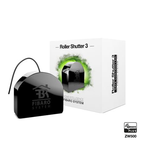
Product Picture


20 - Switch type
This parameter defines as what type the device should treat the switch connected to the S1 and S2 terminals. This parameter is not relevant in gate operating modes (parameter 151 set to 3 or 4). In this case switch always works as a momentary and has to be connected to S1 terminal.Size: 1 byte
Default: 2
Minimum: 0
Maximum: 0
Possible values
| From | To | Desription |
|---|---|---|
| 0 | 0 | momentary switches |
| 1 | 1 | toggle switches |
| 2 | 2 | single, momentary switch (the switch should be connected to S1 terminal) |
24 - Inputs orientation
This parameter allows reversing the operation of switches connected to S1 and S2 without changing the wiring.Size: 1 byte
Default: 0
Minimum: 0
Maximum: 0
Possible values
| From | To | Desription |
|---|---|---|
| 0 | 0 | default (S1 - 1st channel, S2 - 2nd channel) |
| 1 | 1 | reversed (S1 - 2nd channel, S2 - 1st channel) |
25 - Outputs orientation
This parameter allows reversing the operation of Q1 and Q2 without changing the wiring (in case of invalid motor connection) to ensure proper operation.Size: 1 byte
Default: 0
Minimum: 0
Maximum: 0
Possible values
| From | To | Desription |
|---|---|---|
| 0 | 0 | default (Q1 - 1st channel, Q2 - 2nd channel) |
| 1 | 1 | reversed (Q1 - 2nd channel, Q2 - 1st channel) |
30 - Alarm configuration - 1st slot
This parameter determines to which alarm frames and how the device should react. The parameters consist of 4 bytes, three most significant bytes are set according to the official Z-Wave protocol specification. NOTE: Alarm with lower number has the higher priority, thus first alarm will override other alarms with the same type. NOTE: Setting Notification Value to 0xFF will result in launching the action twice: when alarm occurs and is cancelled.Size: 4 bytes
Default: 0
Minimum: 0
Maximum: 0
Possible values
| From | To | Desription |
|---|---|---|
| 1 | 1 | Notification Type |
| 2 | 2 | Notification Status |
| 3 | 3 | Event/State Parameters |
| 4 | 4 | action: 0- no action, 1-open blinds, 2-close blinds |
31 - Alarm configuration - 2nd slot (Water)
This parameter determines to which alarm frames and how the device should react. The parameters consist of 4 bytes, three most significant bytes are set according to the official Z-Wave protocol specification.Size: 4 bytes
Default: 0
Minimum: 0
Maximum: 0
Possible values
| From | To | Desription |
|---|---|---|
| 1 | 1 | Notification Type |
| 2 | 2 | Notification Status |
| 3 | 3 | Event/State Parameters |
| 4 | 4 | action: 0- no action, 1-open blinds, 2-close blinds |
32 - Alarm configuration - 3rd slot (Smoke)
This parameter determines to which alarm frames and how the device should react. The parameters consist of 4 bytes, three most significant bytes are set according to the official Z-Wave protocol specification.Size: 4 bytes
Default: 0
Minimum: 0
Maximum: 0
Possible values
| From | To | Desription |
|---|---|---|
| 1 | 1 | Notification Type |
| 2 | 2 | Notification Status |
| 3 | 3 | Event/State Parameters |
| 4 | 4 | action: 0- no action, 1-open blinds, 2-close blinds |
33 - Alarm configuration - 4th slot (CO)
This parameter determines to which alarm frames and how the device should react. The parameters consist of 4 bytes, three most significant bytes are set according to the official Z-Wave protocol specification.Size: 4 bytes
Default: 0
Minimum: 0
Maximum: 0
Possible values
| From | To | Desription |
|---|---|---|
| 1 | 1 | Notification Type |
| 2 | 2 | Notification Status |
| 3 | 3 | Event/State Parameters |
| 4 | 4 | action: 0- no action, 1-open blinds, 2-close blinds |
34 - Alarm configuration - 5th slot (Heat)
This parameter determines to which alarm frames and how the device should react. The parameters consist of 4 bytes, three most significant bytes are set according to the official Z-Wave protocol specification.Size: 4 bytes
Default: 0
Minimum: 0
Maximum: 0
Possible values
| From | To | Desription |
|---|---|---|
| 1 | 1 | Notification Type |
| 2 | 2 | Notification Status |
| 3 | 3 | Event/State Parameters |
| 4 | 4 | action: 0- no action, 1-open blinds, 2-close blinds |
40 - S1 switch - scenes sent
This parameter determines which actions result in sending scene IDs assigned to them. NOTE: Parameter 40 values may be combined, e.g. 1+2=3 means that scenes for single and double click are sent. NOTE: Enabling triple click for S1 in parameter 40 disables the ability to add/remove via S1.Size: 1 byte
Default: 0
Minimum: 0
Maximum: 0
Possible values
| From | To | Desription |
|---|---|---|
| 1 | 1 | Key pressed 1 time |
| 2 | 2 | Key pressed 2 times |
| 4 | 4 | Key pressed 3 times |
| 8 | 8 | Key hold down and key released |
41 - S2 switch - scenes sent
This parameter determines which actions result in sending scene IDs assigned to them. NOTE: Parameter 41 values may be combined, e.g. 1+2=3 means that scenes for single and double click are sent.Size: 1 byte
Default: 0
Minimum: 0
Maximum: 0
Possible values
| From | To | Desription |
|---|---|---|
| 1 | 1 | Key pressed 1 time |
| 2 | 2 | Key pressed 2 times |
| 4 | 4 | Key pressed 3 times |
| 8 | 8 | Key hold down and key released |
60 - Measuring power consumed by the device itself
This parameter determines whether the power metering should include the amount of active power consumed by the device itself.Size: 1 byte
Default: 0
Minimum: 0
Maximum: 0
Possible values
| From | To | Desription |
|---|---|---|
| 0 | 0 | function inactive |
| 1 | 1 | function active |
61 - Power reports - on change
This parameter determines the minimum change in consumed power that will result in sending new power report to the main controller. For loads under 50W, the parameter is not relevant and reports are sent every 5W change. Power report are sent no often then every 30 seconds.Size: 2 bytes
Default: 15
Minimum: 0
Maximum: 0
Possible values
| From | To | Desription |
|---|---|---|
| 0 | 0 | reports are disabled |
| 1 | 500 | change in power |
62 - Power reports - periodic
This parameter determines in what time intervals the periodic power reports are sent to the main controller. Periodic reports do not depend on power change (parameter 61).Size: 2 bytes
Default: 3600
Minimum: 0
Maximum: 0
Possible values
| From | To | Desription |
|---|---|---|
| 0 | 0 | periodic reports are disabled |
| 30 | 32400 | report interval |
65 - Energy reports - on change
This parameter determines the minimum change in consumed energy that will result in sending new energy report to the main controller.Size: 2 bytes
Default: 10
Minimum: 0
Maximum: 0
Possible values
| From | To | Desription |
|---|---|---|
| 0 | 0 | reports are disabled |
| 1 | 500 | change in energy |
66 - Energy reports - periodic
This parameter determines in what time intervals the periodic energy reports are sent to the main controller. Periodic reports do not depend on energy change (parameter 65).Size: 2 bytes
Default: 3600
Minimum: 0
Maximum: 0
Possible values
| From | To | Desription |
|---|---|---|
| 0 | 0 | periodic reports are disabled |
| 30 | 32400 | report interval |
150 - Force calibration
By setting this parameter to 2 the device enters the calibration mode. The parameter relevant only if the device is set to work in positioning mode (parameter 151 set to 1, 2 or 4).Size: 1 byte
Default: 0
Minimum: 0
Maximum: 0
Possible values
| From | To | Desription |
|---|---|---|
| 0 | 0 | device is not calibrated |
| 1 | 1 | device is calibrated |
| 2 | 2 | force device calibration |
151 - Operating mode
This parameter allows adjusting operation according to the connected device.Size: 1 byte
Default: 1
Minimum: 0
Maximum: 0
Possible values
| From | To | Desription |
|---|---|---|
| 1 | 1 | roller blind (with positioning) |
| 2 | 2 | Venetian blind (with positioning) |
| 3 | 3 | gate (without positioning) |
| 4 | 4 | gate (with positioning) |
| 5 | 5 | roller blind with built-in driver |
| 6 | 6 | roller blind with built-in driver (impulse) |
152 - Venetian blind - time of full turn of the slats
For Venetian blinds (parameter 151 set to 2) the parameter determines time of full turn cycle of the slats. For gates (parameter 151 set to 3 or 4) the parameter determines time after which open gate will start closing automatically (if set to 0, gate will not close). The parameter is irrelevant for other modes.Size: 4 bytes
Default: 150
Minimum: 0
Maximum: 0
Possible values
| From | To | Desription |
|---|---|---|
| 0 | 965535 | time of turn |
153 - Set slats back to previous position
For Venetian blinds (parameter 151 set to 2) the parameter determines slats positioning in various situations. The parameter is irrelevant for other modes. NOTE: If parameter 20 is set to 1 (toggle switch), change value of parameter 153 to 0 for slats to work properly.Size: 1 byte
Default: 1
Minimum: 0
Maximum: 0
Possible values
| From | To | Desription |
|---|---|---|
| 0 | 0 | slats return to previously set position only in case of the main controller operation. |
| 1 | 1 | slats return to previously set position in case of the main controller operation, momentary switch operation, or when the limit switch is reached. |
| 2 | 2 | slats return to previously set position in case of the main controller operation, momentary switch operation, when the limit switch is reached or after receiving the Switch Multilevel Stop control frame |
154 - Delay motor stop after reaching end switch
For blinds (parameter 151 set to 1, 2, 5 or 6) the parameter determines the time after which the motor will be stopped after end switch contacts are closed. For gates (parameter 151 set to 3 or 4) the parameter determines time after which the gate will start closing automatically if S2 contacts are opened (if set to 0, gate will not close).Size: 2 bytes
Default: 10
Minimum: 0
Maximum: 0
Possible values
| From | To | Desription |
|---|---|---|
| 0 | 255 | time |
155 - Motor operation detection
Power threshold to be interpreted as reaching a limit switch.Size: 2 bytes
Default: 10
Minimum: 0
Maximum: 0
Possible values
| From | To | Desription |
|---|---|---|
| 0 | 0 | reaching a limit switch will not be detected |
| 1 | 255 | report interval |
156 - Time of up movement
This parameter determines the time needed for roller blinds to reach the top. For modes with positioning value is set automatically during calibration, otherwise it must be set manually.Size: 4 bytes
Default: 6000
Minimum: 0
Maximum: 0
Possible values
| From | To | Desription |
|---|---|---|
| 1 | 65535 | (0.01 - 655.35s, every 0.01s) - movement time |
157 - Time of down movement
This parameter determines time needed for roller blinds to reach the bottom. For modes with positioning value is set automatically during calibration, otherwise it must be set manually.Size: 4 bytes
Default: 6000
Minimum: 0
Maximum: 0
Possible values
| From | To | Desription |
|---|---|---|
| 1 | 65535 | (0.01 - 655.35s, every 0.01s) - movement time |
To add the device to the Z-Wave network manually: 1. Power the device. 2. Identify the S1 switch. 3. Set the main controller in (Security/non-Security Mode) add mode (see the controller’s manual). 4. Quickly, triple click the S1 switch. 5. If you are adding in Security S2, scan the DSK QR code or input the underlined part of the DSK (label on the bottom of the box). 6. Wait for the adding process to end. 7. Successful adding will be confirmed by the Z-Wave controller’s message. To add the device to the Z-Wave network using Smart Start: 1. Set the main controller in Security S2 Authenticated add mode (see the controller’s manual) 2. Scan the DSK QR code or input the underlined part of the DSK 3. (label on the bottom of the box). 4. Power the device (turn on the mains voltage). 5. LED will start blinking yellow, wait for the adding process to end. 6. Successful adding will be confirmed by the Z-Wave controller’s message.
To remove the device from the Z-Wave network: 1. Make sure the device is powered. 2. Identify the S1 switch. 3. Set the main controller in remove mode (see the controller’s manual). 4. Quickly, triple click the S1 switch. 5. Wait for the removing process to end. 6. Successful removing will be confirmed by the Z-Wave controller’s message.
FIBARO Roller Shutter 3 is powered with mains voltage so it is always awake.
Reset procedure allows to restore the device back to its factory settings, which means all information about the Z-Wave controller and user configuration will be deleted. 1. Switch off the mains voltage (disable the fuse). 2. Remove the device from the wall switch box. 3. Switch on the mains voltage. 4. Press and hold the B-button to enter the menu. 5. Wait for the LED indicator to glow yellow. 6. Quickly release and click the B-button again. 7. After few seconds the device will be restarted, which is signalled with the red LED indicator colour. Please use this procedure only when the network primary controller is missing or otherwise inoperable.""
| Type | Value(s) |
|---|
| Group | Type |
|---|---|
| Power Management | (Refer to parameters): State idle |
| System | (Refer to parameters): State idle |
| Sensor type |
|---|
| Power |
| Meter type |
|---|
| Electric Meter Consumption |