FIBARO
Smart Implant
FGBS-222
Notification Sensor
HW: 2 FW: 5.01
ZM5101
6.81.01
0x010F (271)
0x0502 (1282)
0x1000 (4096)
ZC10-19046414
2019-04-02 20:42:16.780515
N/A
Enhanced 232 Slave
Always On Slave
FIBARO Smart Implant allows to enhance the functionality of wired sensors and other devices by adding Z-Wave network communication.
FIBARO Smart Implant allows to enhance the functionality of wired sensors and other devices by adding Z-Wave network communication. You can connect binary sensors, analog sensors, DS18B20 temperature sensors or DHT22 humidity and temperature sensor to report their readings to the Z-Wave controller. It can also control devices by opening/closing output contacts independently of the inputs. Main features of FIBARO Smart Implant: - Compatible with any Z-Wave or Z-Wave+ Controller, - Supports Z-Wave network Security Modes: S0 with AES-128 encryption and S2 with PRNG-based encryption, - Allows for connecting sensors: o 6 DS18B20 sensors, o 1 DHT sensor, o 2 2-wire analog sensor, o 2 3-wire analog sensor, o 2 binary sensors. - Works as a Z-Wave signal repeater, - Built-in temperature sensor.
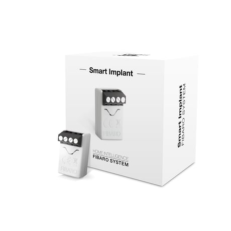
Product Picture


20 - Input 1 - operating mode
This parameter allows to choose mode of 1st input (IN1). Change it depending on connected device.Size: 1 byte
Default: 2
Minimum: 0
Maximum: 0
Possible values
| From | To | Desription |
|---|---|---|
| 0 | 0 | Normally closed alarm input (Notification) |
| 1 | 1 | Normally open alarm input (Notification) |
| 2 | 2 | Monostable button (Central Scene) |
| 3 | 3 | Bistable button (Central Scene) |
| 4 | 4 | Analog input without internal pull-up (Sensor Multilevel) |
| 5 | 5 | Analog input with internal pullup (Sensor Multilevel) |
21 - Input 2 - operating mode
This parameter allows to choose mode of 2nd inputSize: 1 byte
Default: 2
Minimum: 0
Maximum: 0
Possible values
| From | To | Desription |
|---|---|---|
| 0 | 0 | Normally closed alarm input (Notification CC) |
| 1 | 1 | Normally open alarm input (Notification CC) |
| 2 | 2 | Monostable button (Central Scene CC) |
| 3 | 3 | Bistable button (Central Scene CC) |
| 4 | 4 | Analog input without internal pull-up (Sensor Multilevel CC) |
| 5 | 5 | Analog input with internal pullup (Sensor Multilevel CC) |
24 - Inputs orientation
This parameter allows reversing operation of IN1 and IN2 inputs without changing the wiring. Use in case of incorrect wiring.Size: 1 byte
Default: 0
Minimum: 0
Maximum: 0
Possible values
| From | To | Desription |
|---|---|---|
| 0 | 0 | default (IN1 - 1st input, IN2 - 2nd input) |
| 1 | 1 | reversed (IN1 - 2nd input, IN2 - 1st input) |
25 - Outputs orientation
This parameter allows reversing operation of OUT1 and OUT2 inputs without changing the wiring. Use in case of incorrect wiri ng.Size: 1 byte
Default: 0
Minimum: 0
Maximum: 0
Possible values
| From | To | Desription |
|---|---|---|
| 0 | 0 | default (OUT1 - 1st output, OUT2 - 2nd output) |
| 1 | 1 | reversed (OUT1 - 2nd output, OUT2 - 1st output) |
40 - Input 1 - sent scenes
This parameter defines which actions result in sending scene ID and attribute assigned to them (see 9: Activating scenes). Parameter is relevant only if parameter 20 is set to 2 or 3.Size: 1 byte
Default: 0
Minimum: 0
Maximum: 0
Possible values
| From | To | Desription |
|---|---|---|
| 1 | 1 | Key pressed 1 time |
| 2 | 2 | Key pressed 2 times |
| 4 | 4 | Key pressed 3 times |
| 8 | 8 | Key hold down and key released |
41 - Input 2 - sent scenes
This parameter defines which actions result in sending scene ID and attribute assigned to them (see 9: Activating scenes). Parameter is relevant only if parameter 20 is set to 2 or 3.Size: 1 byte
Default: 0
Minimum: 0
Maximum: 0
Possible values
| From | To | Desription |
|---|---|---|
| 1 | 1 | Key pressed 1 time |
| 2 | 2 | Key pressed 2 time |
| 4 | 4 | Key pressed 3 time |
| 8 | 8 | Key hold down and key released |
47 - Input 1 - value sent to 2nd association group when activated
This parameter defines value sent to devices in 2nd association group when IN1 input is triggered (using Basic Command Class).Size: 2 bytes
Default: 255
Minimum: 0
Maximum: 0
Possible values
| From | To | Desription |
|---|---|---|
| 0 | 255 | Value send to devices |
49 - Input 1 - value sent to 2nd association group when deactivated
This parameter defines value sent to devices in 2nd association group when IN1 input is deactivated (using Basic Command Class).Size: 2 bytes
Default: 0
Minimum: 0
Maximum: 0
Possible values
| From | To | Desription |
|---|---|---|
| 0 | 255 | value send to devices |
52 - Input 2 - value sent to 3rd association group when activated
This parameter defines value sent to devices in 3rd association group when IN2 input is triggered (using Basic Command Class).Size: 2 bytes
Default: 255
Minimum: 0
Maximum: 0
Possible values
| From | To | Desription |
|---|---|---|
| 0 | 255 | value send to devices |
54 - Input 2 - value sent to 3rd association group when deactivated
This parameter defines value sent to devices in 2nd association group when IN2 input is deactivated (using Basic Command Class).Size: 2 bytes
Default: 0
Minimum: 0
Maximum: 0
Possible values
| From | To | Desription |
|---|---|---|
| 0 | 255 | value send to devices |
63 - Analog inputs - minimal change to report
This parameter defines minimal change (from the last reported) of analog input value that results in sending new report. Parameter is relevant only for analog inputs (parameter 20 or 21 set to 4 or 5).Size: 1 byte
Default: 5
Minimum: 0
Maximum: 0
Possible values
| From | To | Desription |
|---|---|---|
| 0 | 0 | reporting on change disabled |
| 1 | 100 | (0.1-10V, 0.1V step) |
64 - Analog inputs - periodical reports
This parameter defines reporting period of analog inputs value. Periodical reports are independent from changes in value (parameter 63). Parameter is relevant only for analog inputs (parameter 20 or 21 set to 4 or 5).Size: 2 bytes
Default: 0
Minimum: 0
Maximum: 0
Possible values
| From | To | Desription |
|---|---|---|
| 0 | 0 | periodical reports disabled |
| 60 | 32400 | (60s-9h) |
65 - Internal temperature sensor - minimal change to report
This parameter defines minimal change (from the last reported) of internal temperature sensor value that results in sending new report.Size: 2 bytes
Default: 5
Minimum: 0
Maximum: 0
Possible values
| From | To | Desription |
|---|---|---|
| 0 | 0 | reporting on change disabled |
| 1 | 255 | (0.1-25.5°C) |
66 - Internal temperature sensor - periodical reports
This parameter defines reporting period of internal temperature sensor value. Periodical reports are independent from changes in value (parameter 65).Size: 2 bytes
Default: 0
Minimum: 0
Maximum: 0
Possible values
| From | To | Desription |
|---|---|---|
| 0 | 0 | periodical reports disabled |
| 60 | 32400 | (60s-9h) |
67 - External sensors - minimal change to report
This parameter defines minimal change (from the last reported) of external sensors values (DS18B20 or DHT22) that results in sending new report. Parameter is relevant only for connected DS18B20 or DHT22 sensors.Size: 2 bytes
Default: 5
Minimum: 0
Maximum: 0
Possible values
| From | To | Desription |
|---|---|---|
| 0 | 0 | reporting on change disabled |
| 1 | 255 | (0.1-25.5 units, 0.1) |
68 - External sensors - periodical reports
This parameter defines reporting period of analog inputs value. Periodical reports are independent from changes in value (parameter 67). Parameter is relevant only for connected DS18B20 or DHT22 sensors.Size: 2 bytes
Default: 0
Minimum: 0
Maximum: 0
Possible values
| From | To | Desription |
|---|---|---|
| 0 | 0 | periodical reports disabled |
| 60 | 32400 | (60s-9h) |
150 - Input 1 - sensitivity
This parameter defines the inertia time of IN1 input in alarm modes. Adjust this parameter to prevent bouncing or signal disruptions.Parameter is relevant only if parameter 20 is set to 0 or 1 (alarm mode).Size: 1 byte
Default: 10
Minimum: 0
Maximum: 0
Possible values
| From | To | Desription |
|---|---|---|
| 1 | 100 | (10ms-1000ms, 10ms step) |
151 - Input 2 - sensitivity
This parameter defines the inertia time of IN2 input in alarm modes. Adjust this parameter to prevent bouncing or signal disruptions. Parameter is relevant only if parameter 21 is set to 0 or 1 (alarm mode).Size: 1 byte
Default: 10
Minimum: 0
Maximum: 0
Possible values
| From | To | Desription |
|---|---|---|
| 1 | 100 | (10ms-1000ms, 10ms step) |
152 - Input 1 - delay of alarm cancellation
This parameter defines additional delay of cancelling the alarm on IN1 input. Parameter is relevant only if parameter 20 is set to 0 or 1 (alarm mode).Size: 2 bytes
Default: 0
Minimum: 0
Maximum: 0
Possible values
| From | To | Desription |
|---|---|---|
| 0 | 0 | no delay |
| 1 | 3600 | (in seconds) |
153 - Input 2 - delay of alarm cancellation
This parameter defines additional delay of cancelling the alarm on IN2 input. Parameter is relevant only if parameter 21 is set to 0 or 1 (alarm mode).Size: 2 bytes
Default: 0
Minimum: 0
Maximum: 0
Possible values
| From | To | Desription |
|---|---|---|
| 0 | 0 | no delay |
| 1 | 3600 | (in seconds) |
154 - Output 1 - logic of operation
This parameter defines logic of OUT1 output operation.Size: 1 byte
Default: 0
Minimum: 0
Maximum: 0
Possible values
| From | To | Desription |
|---|---|---|
| 0 | 0 | contacts normally open / closed when active |
| 1 | 1 | contacts normally closed / open when active |
155 - Output 2 - logic of operation
This parameter defines logic of OUT2 output operation.Size: 1 byte
Default: 0
Minimum: 0
Maximum: 0
Possible values
| From | To | Desription |
|---|---|---|
| 0 | 0 | contacts normally open / closed when active |
| 1 | 1 | contacts normally closed / open when active |
156 - Output 1 - auto off
This parameter defines time after which OUT1 will be automatically deactivated.Size: 2 bytes
Default: 0
Minimum: 0
Maximum: 0
Possible values
| From | To | Desription |
|---|---|---|
| 0 | 0 | auto off disabled |
| 1 | 27000 | (0.1s-45min, 0.1s step) |
157 - Output 2 - auto off
This parameter defines time after which OUT2 will be automatically deactivated.Size: 2 bytes
Default: 0
Minimum: 0
Maximum: 0
Possible values
| From | To | Desription |
|---|---|---|
| 0 | 0 | auto off disabled |
| 1 | 27000 | (0.1s-45min, 0.1s step) |
To add the device to the Z-Wave network manually: 1. Power the device. 2. Set the main controller in (Security/non-Security Mode) add mode (see the controller’s manual). 3. Quickly, triple click button on the device housing or switch connected to IN1 or IN2. 4. If you are adding in Security S2 Authenticated, scan the DSK QR code or input the 5-digit PIN code (label on the bottom of the box). 5. LED will start blinking yellow, wait for the adding process to end. 6. Successful adding will be confirmed by the Z-Wave controller’s message. To add the device to the Z-Wave network using Smart Start: 1. Set the main controller in Security S2 Authenticated add mode (see the controller’s manual). 2. Scan the DSK QR code or input the 5-digit PIN code (label on the bottom of the box). 3. Power the device. 4. LED will start blinking yellow, wait for the adding process to end. 5. Successful adding will be confirmed by the Z-Wave controller’s message.
To remove the device from the Z-Wave network: 1. Power the device. 2. Set the main controller into remove mode (see the controller’s manual). 3. Quickly, triple click button on the device housing or switch connected to IN1 or IN2. 4. LED will start blinking yellow, wait for the removing process to end. 5. Successful removing will be confirmed by the Z-Wave controller’s message.
FIBARO Smart Implant is powered using DC power supply unit so it is always awake.
Reset procedure allows to restore the device back to its factory settings, which means all information about the Z-Wave controller and user configuration will be deleted. Resetting the device is not the recommended way of removing the device from the Z-Wave network. Use this procedure only when the network primary controller is missing or inoperable. Certain device removal can be achieved by the procedure of removing described. 1. Press and hold the button to enter the menu. 2. Release button when the device glows yellow. 3. Quickly click the button to confirm. 4. After few seconds the device will be restarted, which is signalled with the red colour.
| Type | Value(s) |
|---|
| Group | Type |
|---|---|
| Home Security | (Refer to parameters): State idle |
| System | (Refer to parameters): State idle |
| Sensor type |
|---|
| General Purpose |