FIBARO
FIBARO Flood Sensor
FGFS-101
Notification Sensor
HW: 1 FW: 3.03:03.03
ZM5202
6.51.07
0x010F (271)
0x0B01 (2817)
0x2003 (8195)
ZC10-19056498
2019-05-19 20:00:22.378676
N/A
Enhanced 232 Slave
Reporting Sleeping Slave
Yes
FIBARO Flood Sensor is a universal, battery or VDC powered, Z-Wave Plus compatible, flood and temperature sensor, designed to be placed on a floor or on a wall.
FIBARO Flood Sensor is a universal, Z-Wave Plus compatible, flood and temperature sensor. The device can be powered using battery, 12/24V DC power supply or both. Flood alarm is sent to the Z-Wave network devices or additionally to any alarm system controller through opening a NC contact using the external power supply. The device has a built-in temperature sensor that allows to monitor ambient temperature. FIBARO Flood Sensor is designed to be placed on the floor or mounted on a wall (in this case Flood Sensor probes should be extended using addition wire). The device has a built-in visual LED indicator and an acoustic alarm. The LED indicator signals flood, operating mode or the Z-Wave network communication range. In addition, the device is equipped with a sensor reporting tilt or movement to the main controller e.g. when someone has taken the Sensor from its original location. FIBARO Flood Sensor is sink-proof, which means it drifts on the water surface and keeps on sending alarm signal in case of substantial inundation of water (if not wired). Flood Sensor is compatible with any Z-Wave or Z-Wave+ Controller.
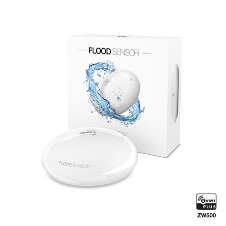
Product Picture


1 - Alarm cancellation delay
Determines time period (in seconds) by which a Flood Sensor will retain the flood state after the flooding itself has ceased. The sensor will keep on reporting flooding to the main controller. This parameter setting does not affect acoustic and visual alarms, which turn off immediately after flooding ceases.Size: 2 bytes
Default: 0
Minimum: 0
Maximum: 0
Possible values
| From | To | Desription |
|---|---|---|
| 0 | 3600 | in seconds, each 1s |
2 - Acoustic and visual signals On / Off in case of flooding
The parameter allows for deactivation visual and acoustic alarm. Parameter allows for increasing a battery life. Setting changes will not affect the sensor’s communication with the main controller - commands to association groups, alarms and reports will still be sent.Size: 1 byte
Default: 3
Minimum: 0
Maximum: 0
Possible values
| From | To | Desription |
|---|---|---|
| 0 | 0 | acoustic and visual alarms inactive |
| 1 | 1 | acoustic alarm inactive, visual alarm active |
| 2 | 2 | acoustic alarm active, visual alarm inactive |
| 3 | 3 | acoustic and visual alarms active |
7 - Requested dimming level / roller blind opening level when sending turn on / open command to 2nd association group devices
Determines the requested “on” level to be sent to devices from 2nd association group upon flood event.Size: 2 bytes
Default: 255
Minimum: 0
Maximum: 0
Possible values
| From | To | Desription |
|---|---|---|
| 1 | 99 | requested level |
| 255 | 255 | turn a device on |
9 - Deactivate turning off devices in 2nd association group & alarm cancellation in 3rd group
This setting decides whether device turn off commands and alarm cancellation notifications will be sent to devices in 2nd and 3rd association groups (respectively) Setting the parameter’s value to 0 disables sending these two commands to associated devices. This means that these devices WILL NOT be informed when the flooding has ceased. It is still possible to cancel alarms in 3rd association group by choosing second (green) menu position (see “Menu & visual indications” on page 10).Size: 1 byte
Default: 1
Minimum: 0
Maximum: 0
Possible values
| From | To | Desription |
|---|---|---|
| 0 | 0 | alarm (flooding) cancellation inactive |
| 1 | 1 | alarm (flooding) cancellation active |
10 - Temperature measurement interval
Time interval (in seconds) between consecutive measurements of battery level and temperature (done by built-in temperature sensor). If the temperature differs from previously reported by a value determined in parameter 12, it will be reported to the Z-Wave controller. In battery mode more significant battery level changes will be reported. Short time intervals mean more frequent communication, which results in shortened battery life. After consecutive FAILED and SUCCESSFUL communication attempts, the Sensor will go to standby mode.Size: 4 bytes
Default: 300
Minimum: 0
Maximum: 0
Possible values
| From | To | Desription |
|---|---|---|
| 1 | 65535 | in seconds |
12 - Temperature measurement hysteresis
Determines a minimum temperature change value (insensitivity level), resulting in a temperature report being sent to the main controller, according to the parameter 10 settings.Size: 2 bytes
Default: 50
Minimum: 0
Maximum: 0
Possible values
| From | To | Desription |
|---|---|---|
| 1 | 1000 | each 0.01°C |
50 - Low temperature alarm threshold
The parameter stores a temperature value, below which visual indicator blinks with a colour determined by a parameter 61 settings. By default the visual indicator blinks blue.Size: 2 bytes
Default: 1500
Minimum: 0
Maximum: 0
Possible values
| From | To | Desription |
|---|---|---|
| -10000 | 10000 | each 0.01°C |
51 - High temperature alarm threshold
The parameter stores a temperature value, above which visual indicator blinks with a colour determined by the parameter 62 settings. By default the visual indicator blinks red.Size: 2 bytes
Default: 3500
Minimum: 0
Maximum: 0
Possible values
| From | To | Desription |
|---|---|---|
| -10000 | 10000 | each 0.01°C |
61 - Low temperature alarm indicator colour
Parameter stores RGB colour value (see the note below for details).Size: 4 bytes
Default: 255
Minimum: 0
Maximum: 0
Possible values
| From | To | Desription |
|---|---|---|
| 0 | 16777215 | Red 16711680; Green 65280; Blue 255; Yellow 16776960; Turquoise 65535; Orange 16750848; White 16777215; Indicator turned off 0 |
62 - High temperature alarm indicator colour
Parameter stores RGB colour value (see the note below for details). NOTE The main controller interprets colours as a sum of its component colours value. Each colours value is a number from 0 to 255. Indicated colour = 65536 RED + 256 GREEN + BLUE Colour Decimal value Red 16711680 Green 65280 Blue 255 Yellow 16776960 Turquoise 65535 Orange 16750848 White 16777215 Indicator turned off 0Size: 4 bytes
Default: 16711680
Minimum: 0
Maximum: 0
Possible values
| From | To | Desription |
|---|---|---|
| 0 | 16777215 | Red 16711680; Green 65280; Blue 255; Yellow 16776960; Turquoise 65535; Orange 16750848; White 16777215; Indicator turned off 0 |
63 - Temperature indication using LED visual indicator
Parameter determines visual indicator’s operation. Setting to 0 turns the temperature LED indication off, saving battery life.Size: 1 byte
Default: 2
Minimum: 0
Maximum: 0
Possible values
| From | To | Desription |
|---|---|---|
| 0 | 0 | visual indicator does not indicate the temperature |
| 1 | 1 | visual indicator indicates the temperature (blink) every Temperature Measurement Interval (parameter 10, constant current and battery) and Wake Up Interval (battery mode) |
| 2 | 2 | visual indicator indicates the temperature continuously, only in constant power mode |
73 - Temperature measurement compensation
Parameter stores a temperature value to be added to or deducted from the current temperature measured by internal temperature sensor in order to compensate the difference between air temperature and temperature at the floor level.Size: 2 bytes
Default: 0
Minimum: 0
Maximum: 0
Possible values
| From | To | Desription |
|---|---|---|
| -10000 | 10000 | °C |
74 - Alarm frame sent to 1st and 4th Association Group activation
(MOVEMENT_TAMPER / BUTTON_TAMPER) The device is able to report tamper alarms resulting from sensor’s tilt/movement or TMP button state change (e.g. taking off the top cover).Size: 1 byte
Default: 2
Minimum: 0
Maximum: 0
Possible values
| From | To | Desription |
|---|---|---|
| 0 | 0 | tamper alarms inactive |
| 1 | 1 | button tamper alarm active |
| 2 | 2 | movement tamper alarm active |
| 3 | 3 | button and movement tampers alarm active |
75 - Alarms signalization duration
The device is capable of automatically turning off alarm signalization after a certain amount of time. Long lasting alarm may reduce batter life, when constantly signalized. The parameter determines time after which alarm will become “quiet” - still active but the device will go into battery saving mode. Visual or acoustic alarm will be reactivated after time specified in the parameter 76. When alarm status ceases, alarm will be turned off immediately. NOTE Parameter 75 is ignored when parameter 2 is set to 0.Size: 4 bytes
Default: 0
Minimum: 0
Maximum: 0
Possible values
| From | To | Desription |
|---|---|---|
| 0 | 0 | alarms active indefinitely |
| 1 | 65535 | time in seconds |
76 - Alarm signalization reactivation period
Parameter determines a time period after which an alarm will be turned back on (in case it was turned off by parameter 75 setting). It will also resend commands to 2nd and 3rd association groups as if the alarm was detected again. NOTE In case a time period set in parameter 76 is shorter than the one specified in parameter 75, the device will not quiet the alarm, it will remain active.Size: 4 bytes
Default: 0
Minimum: 0
Maximum: 0
Possible values
| From | To | Desription |
|---|---|---|
| 0 | 0 | alarm reactivation inactive |
| 1 | 65535 | time in seconds |
77 - Flood sensor functionality turned off
Allows to turn off the internal flood sensor. Tamper and built in temperature sensor will remain active.Size: 1 byte
Default: 0
Minimum: 0
Maximum: 0
Possible values
| From | To | Desription |
|---|---|---|
| 0 | 0 | Default flood sensor operation (flood detection, reactions) |
| 1 | 1 | Built-in flood sensor TURNED OFF (does not change its state in the main controller, does not send alarm notifications nor turn on/off commands to 2nd/3rd association groups with flood state changes. Always visible in the main controller as turned off) |
78 - Associations in Z-Wave network security mode
This parameter defines how commands are sent in specified association groups: as secure or non-secure. Parameter is active only in Z-Wave network security mode. It does not apply to 1st “Lifeline “group.Size: 1 byte
Default: 7
Minimum: 0
Maximum: 0
Possible values
| From | To | Desription |
|---|---|---|
| 0 | 0 | acoustic and visual alarms inactive |
| 0 | 0 | none of the groups sent as secure |
| 1 | 1 | 2nd group, Control, sent as secure |
| 1 | 1 | acoustic alarm inactive, visual alarm active |
| 2 | 2 | acoustic alarm active, visual alarm inactive |
| 2 | 2 | 3rd group, Alarm, sent as secure |
| 3 | 3 | acoustic and visual alarms active |
| 4 | 4 | 4th group, Tamper, sent as secure |
1) Open the cover by turning it counter-clockwise. 2) Remove battery blocker. 3) Place the device within the direct range of your Z-Wave controller. 4) Set the main controller in (security/non-security) add mode (see the controller’s manual). 5) Quickly, triple click the TMP button located inside the casing. 6) Wait for the adding process to end. 7) Successful adding will be confirmed by the Z-Wave controller’s message. 8) Close the cover by turning it clockwise. 9) Place the sensor onto a surface prone to flooding. Three electrodes underneath the device should evenly touch the surface.
1) Open the cover by turning it counter-clockwise. 2) Make sure the device is powered (either by a battery or a DC power supply). 3) Place the device within the direct range of your Z-Wave controller. 4) Set the main controller in remove mode (see the controller’s manual). 5) Quickly, triple click the TMP button located inside the casing. 6) Wait for the removing process to end. 7) Successful removing will be confirmed by the Z-Wave controller’s message.
FIBARO Flood Sensor will wake up at a defined time interval and will always try to communicate with the main controller. There is a possibility to wake up the device manually by clicking the TMP button
1) Open the cover by turning it counter-clockwise. 2) Make sure the device is powered (either by a battery or a DC power supply). 3) Press and hold the TMP button for 15-20 seconds until LED glows yellow (4th menu position). 4) Release and click the TMP button to start the reset procedure. 5) Successful reset will be confirmed with the LED indicator changing colour to red and an acoustic signal. Use reset procedure only if the primary controller is missing or inoperable.
| Type | Value(s) |
|---|
| Group | Type |
|---|---|
| Water Alarm | (Refer to parameters): State idle |
| Sensor type |
|---|
| Air Temperature |