Logic Group A/S
Dimmer Wall Switch
ZDB5100
Wall Controller
HW: 2 FW: 1.01
ZM5101
6.71.03
0x0234 (564)
0x0003 (3)
0x0121 (289)
ZC10-19066525
2019-05-31 18:15:09.367745
N/A
Enhanced 232 Slave
Always On Slave
MATRIX ZDB5100 is a dimmer wall switch module with four backlit pushbuttons. MATRIX is designed to fit into 1-module FUGA® wall boxes (Danish standard).
The front is elegantly designed with a diffused backlight in each of the four pushbuttons. The pushbuttons can light up in all colors which can be used to show the status of a lamp, as orientation light during nighttime, visual alarm and much more. Each pushbutton is a tactile switch designed that can hold up to four functions and control either a wired lamp or other Z-Wave devices, e.g. other light dimmers, roller shutters and power outlets. The light dimmer can dim all dimmable light sources from 0-250 W. MATRIX ZDB5100 is designed to fit into all FUGA® compatible wall boxes and cover frames.
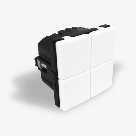
Product Picture


1 - Operating pushbutton(s) for dimmer
This parameter specifies which pushbutton(s) that shall be used to control the built-in dimmer. The parameter is a bitmask, so each of the values can be added together in order to have several pushbuttons to operate the dimmer.Size: 1 byte
Default: 1
Minimum: 0
Maximum: 8
Possible values
| From | To | Desription |
|---|---|---|
| 0 | 0 | No local operation of the dimmer. |
| 1 | 1 | Pushbutton 1 controls the dimmer. |
| 2 | 2 | Pushbutton 2 controls the dimmer. |
| 4 | 4 | Pushbutton 3 controls the dimmer. |
| 8 | 8 | Pushbutton 4 controls the dimmer. |
2 - Duration of dimming
This parameter specifies the duration of a full regulation of the light from 0% to 100%. A regulation of the light with 1% will take 1/100 of the specified duration. This is used when a pushbutton is held-down for controlling the dimming, and when the dimming is fulfilled from other Z-Wave devices.Size: 1 byte
Default: 5
Minimum: 0
Maximum: 255
Possible values
| From | To | Desription |
|---|---|---|
| 0 | 0 | Immediately |
| 1 | 127 | Duration in seconds. |
| 128 | 255 | Duration in minutes (minus 127) from 1 – 128 minutes, where 128 is 1 minute |
3 - Duration of on/off
This parameter specifies the duration when turning the light on or off.Size: 1 byte
Default: 0
Minimum: 0
Maximum: 255
Possible values
| From | To | Desription |
|---|---|---|
| 0 | 0 | Immediately |
| 1 | 127 | Time in seconds |
| 128 | 255 | Time in minutes (minus 127) from 1 – 128 minutes, where 128 is 1 minute |
4 - Dimmer mode
The dimmer can work in three different modes: on/off, leading edge or trailing edge.Size: 1 byte
Default: 1
Minimum: 0
Maximum: 2
Possible values
| From | To | Desription |
|---|---|---|
| 0 | 0 | No dimming, only on/off (0/100%). |
| 1 | 1 | Trailing edge dimming |
| 2 | 2 | Leading edge dimming |
5 - Dimmer minimum level
This parameter specifies the actual level of the dimmer output when set to 0%.Size: 1 byte
Default: 0
Minimum: 0
Maximum: 99
Possible values
| From | To | Desription |
|---|---|---|
| 0 | 99 | Corresponds to 0 – 99% |
6 - Dimmer maximum level
This parameter specifies the actual level of the dimmer output when set to 99%.Size: 1 byte
Default: 99
Minimum: 0
Maximum: 99
Possible values
| From | To | Desription |
|---|---|---|
| 0 | 99 | Corresponds to 0 – 99% |
7 - Central Scene notifications
This parameter can be used for disabling Central Scene notifications.Size: 1 byte
Default: 1
Minimum: 0
Maximum: 1
Possible values
| From | To | Desription |
|---|---|---|
| 0 | 0 | Notifications are disabled |
| 1 | 1 | Notifications are enabled |
8 - Double-activation functionality
This parameter specifies the reaction when double-activating the pushbuttons.Size: 1 byte
Default: 1
Minimum: 0
Maximum: 1
Possible values
| From | To | Desription |
|---|---|---|
| 0 | 0 | Double-activation disabled |
| 1 | 1 | Double-activation sets light to 100% |
9 - Triple-activation of pushbutton 1
This parameter can be used for disabling the Z-Wave network add/remove process when triple-activating pushbutton 1. If disabled, the triple-activation functionality can be used as a Central Scene notification.Size: 1 byte
Default: 1
Minimum: 0
Maximum: 1
Possible values
| From | To | Desription |
|---|---|---|
| 0 | 0 | Triple-activation of pushbutton 1, does not start the add/remove process. |
| 1 | 1 | Triple-activation of pushbutton 1, starts the add/remove process |
11 - Pushbutton debounce timer
Pushbutton input debounce time in 0.01 seconds resolution.Size: 1 byte
Default: 5
Minimum: 0
Maximum: 255
Possible values
| From | To | Desription |
|---|---|---|
| 0 | 255 | 0 – 2.55 seconds. Default is 5, which equals to a debounce-filter on 50 milliseconds (0.05 seconds) |
12 - Pushbutton press threshold time
Specifies the time that a pushbutton must be activated before it is detected as pressed. Resolution is in 0.01 seconds.Size: 1 byte
Default: 20
Minimum: 0
Maximum: 255
Possible values
| From | To | Desription |
|---|---|---|
| 0 | 255 | 0 – 2.55 seconds. Default is 20, which equals to 200 milliseconds (0.2 seconds). |
13 - Pushbutton held threshold time
Specifies the time that a pushbutton must have been activated before it is accepted as “held-down”. Resolution is 0.01 seconds.Size: 1 byte
Default: 50
Minimum: 0
Maximum: 255
Possible values
| From | To | Desription |
|---|---|---|
| 0 | 255 | 0 – 2.55 seconds. Default is 50, which equals to 500 milliseconds (0,5 seconds). |
14 - Global brightness control
This parameter specifies a common brightness for each of the three base colours for all four pushbutton indicators. Byte 1: Red brightness. Byte 2: Green brightness. Byte 3: Blue brightness. Byte 4: Not used – must be set to 0.Size: 4 bytes
Default: 255
Minimum: 0
Maximum: 255
Possible values
| From | To | Desription |
|---|---|---|
| 0 | 255 | Byte 3: Brightness level for the blue colour in the 4 indicator groups. (Default is 255) |
| 0 | 0 | Byte 4: Not used – must be set to 0. |
| 0 | 255 | Byte1: Brightness level for the red colour in the 4 indicator groups. (Default is 255) |
| 0 | 255 | Byte 2: Brightness level for the green colour in the 4 indicator groups. (Default is 255) |
15 - Associations groups, transmission when included secure
This parameter specifies if commands are transmitted as a secure message for each of the association groups. This parameter is only used when the device is included in security mode (either S0 or S2). The values are bitmasks that can be added up to select several options.Size: 2 bytes
Default: 8191
Minimum: 0
Maximum: 8191
Possible values
| From | To | Desription |
|---|---|---|
| 0 | 0 | All messages in all groups are sent as insecure. |
| 1 | 1 | Messages in association group 2 is sent as secure. |
| 2 | 2 | Messages in association group 3 is sent as secure. |
| 4 | 4 | Messages in association group 4 is sent as secure. |
| 8 | 8 | Messages in association group 5 is sent as secure. |
| 16 | 16 | Messages in association group 6 is sent as secure. |
| 32 | 32 | Messages in association group 7 is sent as secure. |
| 64 | 64 | Messages in association group 8 is sent as secure. |
| 128 | 128 | Messages in association group 9 is sent as secure. |
| 256 | 256 | Messages in association group 10 is sent as secure. |
| 512 | 512 | Messages in association group 11 is sent as secure. |
| 1024 | 1024 | Messages in association group 12 is sent as secure. |
| 2048 | 2048 | Messages in association group 13 is sent as secure. |
| 4096 | 4096 | Messages in association group 14 is sent as secure. |
| 8191 | 8191 | Messages in all association groups are sent as secure. |
16 - Pushbutton 1 functionality
This parameter specifies the functionality of pushbutton 1.Size: 1 byte
Default: 0
Minimum: 0
Maximum: 4
Possible values
| From | To | Desription |
|---|---|---|
| 0 | 0 | Standard toggle-function, the state is switched between on and off, dimming up and down. |
| 1 | 1 | Automatic turn off after the time has expired (staircase lighting function), the time is specified in the next configuration parameter. |
| 2 | 2 | Automatic turn on after the time has expired, the time is specified in the next configuration parameter. |
| 3 | 3 | Always turn off or dim down . Using this parameter, the pushbutton can only send ‘off’ or ‘dim down’ commands. Use this in pair with another pushbutton with value 4 (see chapter 2.6 in the manual) |
| 4 | 4 | Always turn on or dim up. Using this parameter, the pushbutton can only send ‘on’ or ‘dim up’ commands. Use this in pair with another pushbutton with value 3 (see chapter 2.6 in the manual) |
17 - Timer value for pushbutton 1
This parameter specifies the time used in previous configuration parameter. This parameter is only applicable if previous parameter has value 1 or 2.Size: 2 bytes
Default: 300
Minimum: 0
Maximum: 43200
Possible values
| From | To | Desription |
|---|---|---|
| 0 | 43200 | Specifies the time in seconds. Default is 300 = 5 minutes. |
18 - Multi-Level Switch Set values for pushbutton 1
Byte 1: Enable / Disable Byte 2: Upper switch value Byte 3: Lower switch value Byte 4: Not used – must be set to 0.Size: 1 byte
Default: 0
Minimum: 0
Maximum: 255
Possible values
| From | To | Desription |
|---|---|---|
| 0 | 0 | Byte 1: Disabled – A single activation of the button will not result in commands are sent to devices in association group 4. |
| 0 | 99 | Byte 2: When single pressing the button for ON, a Multilevel Switch Set with this value will be send to devices in association group 4. |
| 0 | 99 | Byte 3: When single pressing the button for OFF, a Multilevel Switch Set with this value will be send to devices in association group 4. (Default = 0) |
| 0 | 0 | Byte 4: Not used – must be set to 0 |
| 1 | 1 | Byte 1: Enabled – A single activation will result in commands are sent to devices in association group 4, they will receive commands with the values set below. (Default). |
| 255 | 255 | Byte 2: When single pressing the button for ON, a Multilevel Switch Set with this value will be send to devices in association group 4. (Default = 255) |
19 - Binary Switch Set support for pushbutton 1
This parameter specifies how received Binary Switch Set commands are handled.Size: 1 byte
Default: 0
Minimum: 0
Maximum: 2
Possible values
| From | To | Desription |
|---|---|---|
| 0 | 0 | Binary Switch Set only controls the pushbutton indicator LEDs, ON/OFF |
| 1 | 1 | Binary Switch Set controls the internal switch status and the pushbutton indicator LEDs |
| 2 | 2 | Binary Switch Set is handled as if the user had activated the pushbutton, including transmission of commands via the association groups |
20 - Pushbutton 1 LED indication
This parameter specifies how the LED indication is controlled.Size: 1 byte
Default: 7
Minimum: 0
Maximum: 7
Possible values
| From | To | Desription |
|---|---|---|
| 0 | 0 | Internal LED control is disabled, only external commands control the indication |
| 1 | 1 | The LED indication follows the switch status |
| 2 | 2 | The LED indication follows the switch status – with inverted functionality |
| 3 | 3 | Same as 1 |
| 4 | 4 | Same as 2 |
| 5 | 5 | The LED indication follows the status of the internal dimmer, ON or OFF |
| 6 | 6 | The LED indication follows the status of the internal dimmer with inverted functionality, ON or OFF |
| 7 | 7 | The LED indicator is ON for 5 seconds when the pushbutton is activated |
21 - Colour commands for pushbutton 1 LED indication
This parameter specifies how Command Class Switch Color commands are handled.Size: 1 byte
Default: 1
Minimum: 0
Maximum: 2
Possible values
| From | To | Desription |
|---|---|---|
| 0 | 0 | Direct control; the LED indication shows the received colour immediately, until the pushbutton is activated |
| 1 | 1 | Colour command sets the colour for OFF indication |
| 2 | 2 | Colour command sets the colour for ON indication |
22 - ON indication RGB-saturation for pushbutton 1
This parameter specifies the saturation levels for the red, green and blue LEDs, when ON status is indicated. (Default is the ON-state indicated by a 50% blue colour). Byte 1: Colour saturation, red. Byte 2: Colour saturation, green. Byte 3: Colour saturation, blue. Byte 4: LED control.Size: 4 bytes
Default: 255
Minimum: 0
Maximum: 255
Possible values
| From | To | Desription |
|---|---|---|
| 0 | 255 | Byte 4: LED indicator control; see the application note about this parameter. (Default is 0) |
| 0 | 255 | Byte 1: Specifies the saturation for the red LEDs. (Default is 0) |
| 0 | 255 | Byte 2: Specifies the saturation for the green LEDs. (Default is 0) |
| 0 | 255 | Byte 3: Specifies the saturation for the blue LEDs. (Default is 127) |
23 - OFF indication RGB-saturation for pushbutton 1
This parameter specifies the saturation levels for the red, green and blue LEDs, when OFF status is indicated. (Default is the OFF-state indicated as a low white light on 5%). Byte 1: Colour saturation, red. Byte 2: Colour saturation, green. Byte 3: Colour saturation, blue. Byte 4: LED control.Size: 4 bytes
Default: 47
Minimum: 0
Maximum: 255
Possible values
| From | To | Desription |
|---|---|---|
| 0 | 255 | Byte 3: Specifies the saturation for the blue LEDs. (Default is 47) |
| 0 | 255 | Byte 4: LED indicator control; see the application note about this parameter. (Default is 0) |
| 0 | 255 | Byte 1: Specifies the saturation for the red LEDs. (Default is 47) |
| 0 | 255 | Byte 2: Specifies the saturation for the green LEDs. (Default is 47) |
24 - Pushbutton 2 functionality
This parameter specifies the functionality of pushbutton 2.Size: 1 byte
Default: 0
Minimum: 0
Maximum: 4
Possible values
| From | To | Desription |
|---|---|---|
| 0 | 0 | Standard toggle-function, the state is switched between on and off, dimming up and down. |
| 1 | 1 | Automatic turn off after the time has expired (staircase lighting function), the time is specified in the next configuration parameter. |
| 2 | 2 | Automatic turn on after the time has expired, the time is specified in the next configuration parameter. |
| 3 | 3 | Always turn off or dim down. Using this parameter, the pushbutton can only send ‘off’ or ‘dim down’ commands. Use this in pair with another pushbutton with value 4 (see chapter 2.6 in the manual) |
| 4 | 4 | Always turn on or dim up. Using this parameter, the pushbutton can only send ‘on’ or ‘dim up’ commands. Use this in pair with another pushbutton with value 3 (see chapter 2.6 in the manual) |
25 - Timer value for pushbutton 2
This parameter specifies the time used in previous configuration parameter. This parameter is only applicable if previous parameter has value 1 or 2.Size: 2 bytes
Default: 300
Minimum: 0
Maximum: 43200
Possible values
| From | To | Desription |
|---|---|---|
| 0 | 0 | Enhanced LED control is disabled |
| 0 | 43200 | Specifies the time in seconds. Default is 300 = 5 minutes |
| 1 | 1 | Enhanced LED control is enabled |
26 - Multi-Level Switch Set values for pushbutton 2
Byte 1: Enable / Disable. Byte 2: Upper switch value. Byte 3: Lower switch value. Byte 4: Not used – must be set to 0.Size: 4 bytes
Default: 0
Minimum: 0
Maximum: 255
Possible values
| From | To | Desription |
|---|---|---|
| 0 | 0 | Byte 1: Disabled – A single activation of the pushbutton will not send commands to devices in association group 4 |
| 0 | 0 | Byte 4: Not used – must be set to 0. |
| 0 | 99 | Byte 3: When single pressing the pushbutton for OFF, a Multilevel Switch Set with this value will be send to devices in association group 4. (Default = 0) |
| 0 | 99 | Byte 2: When single pressing the pushbutton for ON, a Multilevel Switch Set with this value will be send to devices in association group 4. (Default = 255) |
| 1 | 1 | Byte 1: Enabled – A single activation will send commands to devices in association group 4. Devices will receive commands with the values set in Byte 2 and 3 (Default) |
| 255 | 255 | Byte 2: When single pressing the pushbutton for ON, a Multilevel Switch Set with this value will be send to devices in association group 4. (Default = 255) |
27 - Binary Switch Set support for pushbutton 2
This parameter specifies how received Binary Switch Set commands are handled.Size: 1 byte
Default: 0
Minimum: 0
Maximum: 2
Possible values
| From | To | Desription |
|---|---|---|
| 0 | 0 | Binary Switch Set only controls the button indicator LEDs, ON/OFF |
| 1 | 1 | Binary Switch Set controls the internal switch status and the button indicator LEDs |
| 2 | 2 | Binary Switch Set is handled as if the user had activated the button, including transmission of commands via the association groups |
28 - Pushbutton 2 LED indication
This parameter specifies how the LED indication is controlled.Size: 1 byte
Default: 7
Minimum: 0
Maximum: 7
Possible values
| From | To | Desription |
|---|---|---|
| 0 | 0 | Internal LED control is disabled, only external commands control the indication |
| 1 | 1 | The LED indication follows the switch status |
| 2 | 2 | The LED indication follows the switch status – with inverted functionality |
| 3 | 3 | Same as 1 |
| 4 | 4 | Same as 2 |
| 5 | 5 | The LED indication follows the status of the internal dimmer, ON or OFF |
| 6 | 6 | The LED indication follows the status of the internal dimmer with inverted functionality, ON or OFF |
| 7 | 7 | The LED indicator is ON for 5 seconds when the pushbutton is activated |
29 - Colour commands for pushbutton 2 LED indication
This parameter specifies how Command Class Switch Color commands is handled.Size: 1 byte
Default: 1
Minimum: 0
Maximum: 2
Possible values
| From | To | Desription |
|---|---|---|
| 0 | 0 | Direct control; the LED indication shows the received colour immediately, until the pushbutton is activated |
| 1 | 1 | Colour command sets the colour for OFF indication |
| 2 | 2 | Colour command sets the colour for ON indication |
30 - ON indication RGB-saturation for pushbutton 2
This parameter specifies the saturation levels for the red, green and blue LEDs, when ON status is indicated. (Default is the ON-state indicated by a 50% blue colour). Byte 1: Colour saturation, red. Byte 2: Colour saturation, green. Byte 3: Colour saturation, blue. Byte 4: LED control.Size: 4 bytes
Default: 0
Minimum: 0
Maximum: 255
Possible values
| From | To | Desription |
|---|---|---|
| 0 | 255 | Byte 1:Specifies the saturation for the red LEDs. (Default is 0) |
| 0 | 255 | Byte 2: Specifies the saturation for the green LEDs. (Default is 0) |
| 0 | 255 | Byte 3: Specifies the saturation for the blue LEDs. (Default is 127) |
| 0 | 255 | Byte 4: LED indicator control; see the application note about this parameter. (Default is 0) |
31 - OFF indication RGB-saturation for pushbutton 2
This parameter specifies the saturation levels for the red, green and blue LEDs, when OFF status is indicated. (Default is the OFF-state indicated as a low white light on 5%). Byte 1: Colour saturation, red. Byte 2: Colour saturation, green. Byte 3: Colour saturation, blue. Byte 4: LED control.Size: 4 bytes
Default: 255
Minimum: 0
Maximum: 255
Possible values
| From | To | Desription |
|---|---|---|
| 0 | 255 | Byte 4: LED indicator control; see the application note about this parameter (Default is 0) |
| 0 | 255 | Byte 2: Specifies the saturation for the green LEDs (Default is 47) |
| 0 | 255 | Byte 3: Specifies the saturation for the blue LEDs (Default is 47) |
| 0 | 255 | Byte 1: Specifies the saturation for the red LEDs (Default is 47) |
32 - Pushbutton 3 functionality
This parameter specifies the functionality of pushbutton 3.Size: 1 byte
Default: 0
Minimum: 0
Maximum: 4
Possible values
| From | To | Desription |
|---|---|---|
| 0 | 0 | Standard toggle-function, the state is switched between on and off, dimming up and down |
| 1 | 1 | Automatic turn off after the time has expired (staircase lighting function), the time is specified in the next configuration parameter. |
| 2 | 2 | Automatic turn on after the time has expired, the time is specified in the next configuration parameter. |
| 3 | 3 | Always turn off or dim down. Using this parameter, the pushbutton can only send ‘off’ or ‘dim down’ commands. Use this in pair with another pushbutton with value 4 (see chapter 2.6 in the manual) |
| 4 | 4 | Always turn on or dim up. Using this parameter, the pushbutton can only send ‘on’ or ‘dim up’ commands. Use this in pair with another pushbutton with value 3 (see chapter 2.6 in the manual) |
33 - Timer value for pushbutton 3
This parameter specifies the time used in previous configuration parameter. This parameter is only applicable if previous parameter has value 1 or 2.Size: 2 bytes
Default: 300
Minimum: 0
Maximum: 43200
Possible values
| From | To | Desription |
|---|---|---|
| 0 | 43200 | Specifies the time in seconds. Default is 300 = 5 minutes |
34 - Multi-Level Switch Set values for pushbutton 3
Byte 1: Enable / Disable. Byte 2: Upper switch value. Byte 3: Lower switch value. Byte 4: Not used – must be set to 0.Size: 4 bytes
Default: 0
Minimum: 0
Maximum: 255
Possible values
| From | To | Desription |
|---|---|---|
| 0 | 0 | Byte 4: Not used – must be set to 0 |
| 0 | 99 | Byte 3: When single pressing the pushbutton for OFF, a Multilevel Switch Set with this value will be send to devices in association group 4 (Default = 0) |
| 0 | 0 | Byte 1: Disabled – A single activation of the pushbutton will not send commands to devices in association group 4 |
| 0 | 99 | Byte 2: When single pressing the pushbutton for ON, a Multilevel Switch Set with this value will be send to devices in association group 4 |
| 1 | 1 | Byte 1: Enabled – A single activation will send commands to devices in association group 4. Devices will receive commands with the values set in Byte 2 and 3 (default) |
| 255 | 255 | Byte 2: When single pressing the pushbutton for ON, a Multilevel Switch Set with this value will be send to devices in association group 4 (default) |
35 - Binary Switch Set support for pushbutton 3
This parameter specifies how received Binary Switch Set commands are handled.Size: 1 byte
Default: 0
Minimum: 0
Maximum: 2
Possible values
| From | To | Desription |
|---|---|---|
| 0 | 0 | Binary Switch Set only controls the pushbutton indicator LEDs, ON/OFF |
| 1 | 1 | Binary Switch Set controls the internal switch status and the pushbutton indicator LEDs |
| 2 | 2 | Binary Switch Set is handled as if the user had activated the pushbutton, including transmission of commands via the association groups |
36 - Pushbutton 3 LED indication
This parameter specifies how the LED indication is controlled.Size: 1 byte
Default: 7
Minimum: 0
Maximum: 7
Possible values
| From | To | Desription |
|---|---|---|
| 0 | 0 | Internal LED control is disabled, only external commands control the indication |
| 1 | 1 | The LED indication follows the switch status |
| 2 | 2 | The LED indication follows the switch status – with inverted functionality |
| 3 | 3 | Same as 1 |
| 4 | 4 | Same as 2 |
| 5 | 5 | The LED indication follows the status of the internal dimmer, ON or OFF |
| 6 | 6 | The LED indication follows the status of the internal dimmer with inverted functionality, ON or OFF |
| 7 | 7 | The LED indicator is ON for 5 seconds when the pushbutton is activated |
37 - Colour commands for pushbutton 3 LED indication
This parameter specifies how Command Class Switch Color commands is handledSize: 1 byte
Default: 1
Minimum: 0
Maximum: 2
Possible values
| From | To | Desription |
|---|---|---|
| 0 | 0 | Direct control; the LED indication shows the received colour immediately, until the pushbutton is activated |
| 1 | 1 | Colour command sets the colour for OFF indication |
| 2 | 2 | Colour command sets the colour for ON indication |
38 - ON indication RGB-saturation for pushbutton 3
This parameter specifies the saturation levels for the red, green and blue LEDs, when ON status is indicated. (Default is the ON-state indicated by a 50% blue colour). Byte 1: Colour saturation, red. Byte 2: Colour saturation, green. Byte 3: Colour saturation, blue. Byte 4: LED control.Size: 4 bytes
Default: 127
Minimum: 0
Maximum: 255
Possible values
| From | To | Desription |
|---|---|---|
| 0 | 255 | Byte 1: Specifies the saturation for the red LEDs. (Default is 0) |
| 0 | 255 | Byte 3: Specifies the saturation for the blue LEDs. (Default is 127) |
| 0 | 255 | Byte 2: Specifies the saturation for the green LEDs. (Default is 0) |
| 0 | 255 | Byte 4: LED indicator control; see the application note about this parameter. (Default is 0) |
39 - OFF indication RGB-saturation for pushbutton 3
This parameter specifies the saturation levels for the red, green and blue LEDs, when OFF status is indicated. (Default is the OFF-state indicated as a low white light on 5%). Byte 1: Colour saturation, red. Byte 2: Colour saturation, green. Byte 3: Colour saturation, blue. Byte 4: LED control.Size: 4 bytes
Default: 47
Minimum: 0
Maximum: 255
Possible values
| From | To | Desription |
|---|---|---|
| 0 | 255 | Byte 2: Specifies the saturation for the green LEDs. (Default is 47) |
| 0 | 255 | Byte 3: Specifies the saturation for the blue LEDs. (Default is 47) |
| 0 | 255 | Byte 4: LED indicator control; see the application note about this parameter. (Default is 0) |
| 0 | 255 | Byte 1: Specifies the saturation for the red LEDs. (Default is 47). |
40 - Pushbutton 4 functionality
This parameter specifies the functionality of pushbutton 4.Size: 1 byte
Default: 0
Minimum: 0
Maximum: 4
Possible values
| From | To | Desription |
|---|---|---|
| 0 | 0 | Standard toggle-function, the state is switched between on and off, dimming up and down |
| 1 | 1 | Automatic turn off after the time has expired (staircase lighting function), the time is specified in the next configuration parameter. |
| 2 | 2 | Automatic turn on after the time has expired, the time is specified in the next configuration parameter. |
| 3 | 3 | Always turn off or dim down. Using this parameter, the pushbutton can only send ‘off’ or ‘dim down’ commands. Use this in pair with another pushbutton with value 4 (see chapter 2.6 in the manual). |
| 4 | 4 | Always turn on or dim up. Using this parameter, the pushbutton can only send ‘on’ or ‘dim up’ commands. Use this in pair with another pushbutton with value 3 (see chapter 2.6 in the manual). |
41 - Timer value for pushbutton 4
This parameter specifies the time used in previous configuration parameter. This parameter is only applicable if previous parameter has value 1 or 2.Size: 2 bytes
Default: 300
Minimum: 0
Maximum: 43200
Possible values
| From | To | Desription |
|---|---|---|
| 0 | 43200 | Specifies the time in seconds. Default is 300 = 5 minutes |
42 - Multi-Level Switch Set values for pushbutton 4
Byte 1: Enable / Disable. Byte 2: Upper switch value. Byte 3: Lower switch value. Byte 4: Not used – must be set to 0.Size: 4 bytes
Default: 255
Minimum: 0
Maximum: 255
Possible values
| From | To | Desription |
|---|---|---|
| 0 | 0 | Byte 4: Not used – must be set to 0. |
| 0 | 99 | Byte 2: When single pressing the pushbutton for ON, a Multilevel Switch Set with this value will be send to devices in association group 4 |
| 0 | 0 | Byte 1: Disabled – A single activation of the pushbutton will not send commands to devices in association group 4. |
| 0 | 99 | Byte 3: When single pressing the pushbutton for OFF, a Multilevel Switch Set with this value will be send to devices in association group 4. (Default = 0) |
| 1 | 1 | Byte 1: Enabled – A single activation will send commands to devices in association group 4. Devices will receive commands with the values set in Byte 2 and 3 (Default). |
| 255 | 255 | Byte 2: When single pressing the pushbutton for ON, a Multilevel Switch Set with this value will be send to devices in association group 4. (Default) |
43 - Binary Switch Set support for pushbutton 4
This parameter specifies how received Binary Switch Set commands are handled.Size: 1 byte
Default: 2
Minimum: 0
Maximum: 2
Possible values
| From | To | Desription |
|---|---|---|
| 0 | 0 | Binary Switch Set only controls the pushbutton indicator LEDs, ON/OFF |
| 1 | 1 | Binary Switch Set controls the internal switch status and the pushbutton indicator LEDs |
| 2 | 2 | Binary Switch Set is handled as if the user had activated the pushbutton, including transmission of commands via the association groups |
44 - Pushbutton 4 LED indication
This parameter specifies how the LED indication is controlled.Size: 1 byte
Default: 7
Minimum: 0
Maximum: 7
Possible values
| From | To | Desription |
|---|---|---|
| 0 | 0 | Internal LED control is disabled, only external commands control the indication. |
| 1 | 1 | The LED indication follows the switch status |
| 2 | 2 | The LED indication follows the switch status – with inverted functionality |
| 3 | 3 | Same as 1 |
| 4 | 4 | Same as 2 |
| 5 | 5 | The LED indication follows the status of the internal dimmer, ON or OFF |
| 6 | 6 | The LED indication follows the status of the internal dimmer with inverted functionality, ON or OFF |
| 7 | 7 | The LED indicator is ON for 5 seconds when the pushbutton is activated |
45 - Colour commands for pushbutton 4 LED indication
This parameter specifies how Command Class Switch Color commands are handled.Size: 1 byte
Default: 1
Minimum: 0
Maximum: 2
Possible values
| From | To | Desription |
|---|---|---|
| 0 | 0 | Direct control; the LED indication shows the received colour immediately, until the pushbutton is activated |
| 1 | 1 | Colour command sets the colour for OFF indication |
| 2 | 2 | Colour command sets the colour for ON indication |
46 - ON indication RGB-saturation for pushbutton 4
This parameter specifies the saturation levels for the red, green and blue LEDs, when ON status is indicated. (Default is the ON-state indicated by a 50% blue colour). Byte 1: Colour saturation, red. Byte 2: Colour saturation, green. Byte 3: Colour saturation, blue. Byte 4: LED control.Size: 4 bytes
Default: 255
Minimum: 0
Maximum: 255
Possible values
| From | To | Desription |
|---|---|---|
| 0 | 255 | Byte 1: Specifies the saturation for the red LEDs. (Default is 0) |
| 0 | 255 | Byte 2: Specifies the saturation for the green LEDs. (Default is 0) |
| 0 | 255 | Byte 3: Specifies the saturation for the blue LEDs. (Default is 127) |
| 0 | 255 | Byte 4: LED indicator control; see the application note about this parameter. (Default is 0) |
47 - OFF indication RGB-saturation for pushbutton 4
This parameter specifies the saturation levels for the red, green and blue LEDs, when OFF status is indicated. (Default is the OFF-state indicated as a low white light on 5%). Byte 1: Colour saturation, red. Byte 2: Colour saturation, green. Byte 3: Colour saturation, blue. Byte 4: LED control.Size: 4 bytes
Default: 255
Minimum: 0
Maximum: 255
Possible values
| From | To | Desription |
|---|---|---|
| 0 | 255 | Byte 1: Specifies the saturation for the red LEDs. (Default is 47) |
| 0 | 255 | Byte 2: Specifies the saturation for the green LEDs. (Default is 47) |
| 0 | 255 | Byte 4: LED indicator control; see the application note about this parameter. (Default is 0) |
| 0 | 255 | Byte 3: Specifies the saturation for the blue LEDs. (Default is 47) |
Remove white pushbutton cover and press on the center switch with a non-conductive object. The LEDs will now start blinking on pushbutton 1 (upper left pushbutton)
Remove white pushbutton cover and press on the center switch with a non-conductive object. The LEDs will now start blinking on pushbutton 1 (upper left pushbutton)
Remove white pushbutton cover and long-press the center switch for 10 seconds with a non-conductive object. Please use this procedure only when the network primary controller is missing or otherwise inoperable.
| Type | Value(s) |
|---|